Kips: Kawasaki Integrated Power-Valve System
disclaimer: i am not liable for what you do to your bike, or any dmage you cause from info here, and all that fun stuff, this is not a replacement for the manual, go get a real kawi manual
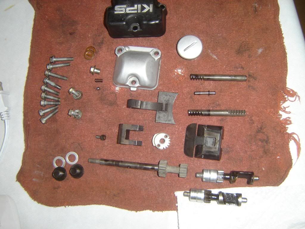
here are the parts that make up a kdx powervalve, the advancer shaft cover is missing from the pic, but everything else is there
http://i222.photobucket.com/albums/dd18 ... nd2001.jpg
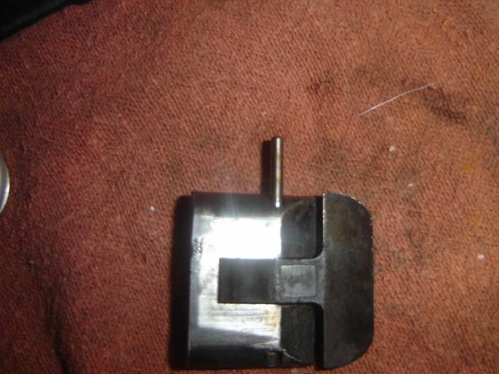
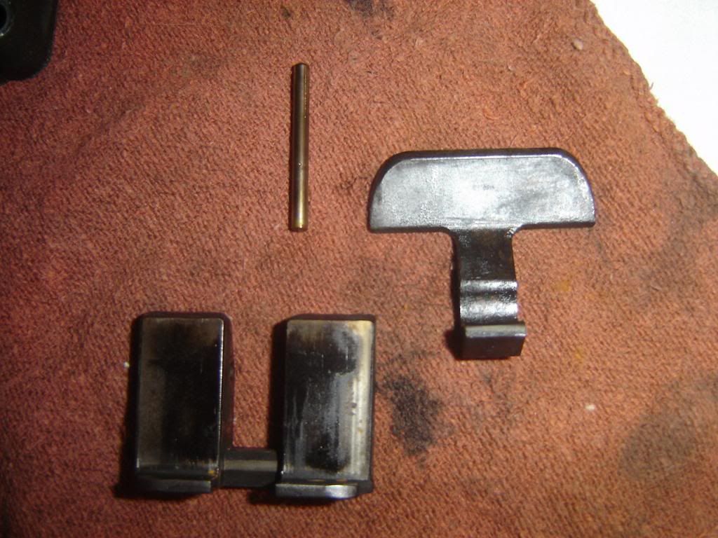
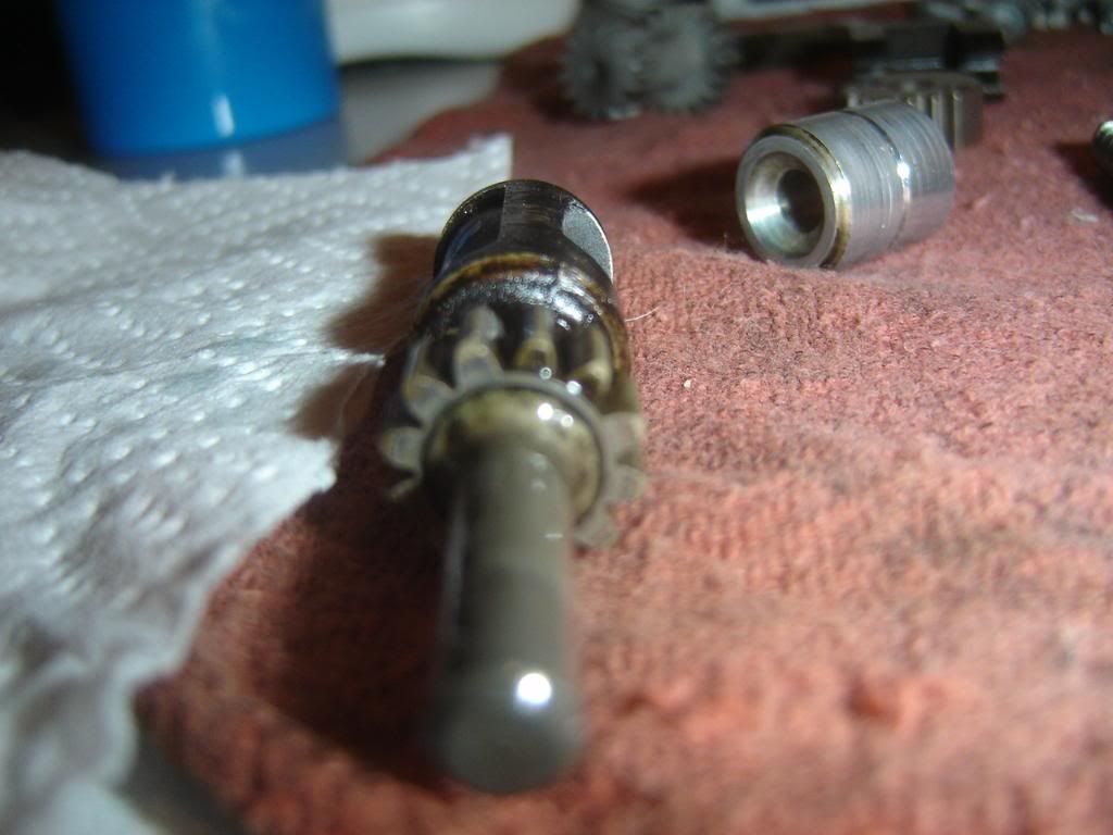
this is the main valve
http://i222.photobucket.com/albums/dd18 ... nd2002.jpg
you can pull that pin out to separate the 2 peices for cleaning
http://i222.photobucket.com/albums/dd18 ... nd2003.jpg
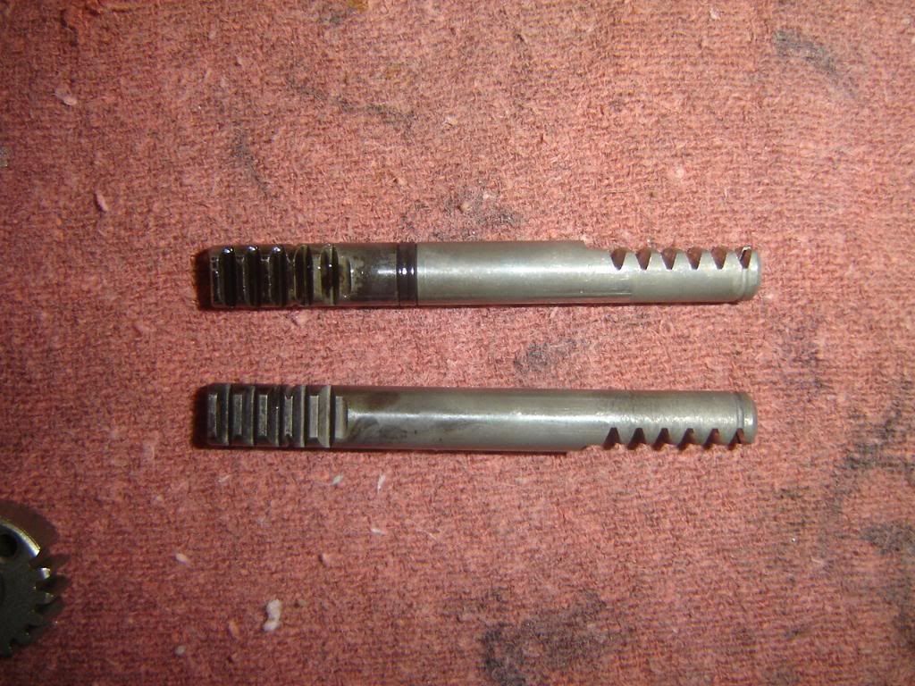
subvalves: the sublaves and their shafts are different, and it does matter where they go. for simplicity, i will refer to everything as left and right side as you are sitting on the bike. the subvalves shafts will not work if they are swapped, the teeth on the shaft will be pointing in the wrong direction when you install them, and you will not be able to get the gears on. the subvlaves can be mixed up and the bike will run and nothing will get dmaged, but the powervalve will not work correclty, and you will loose power.
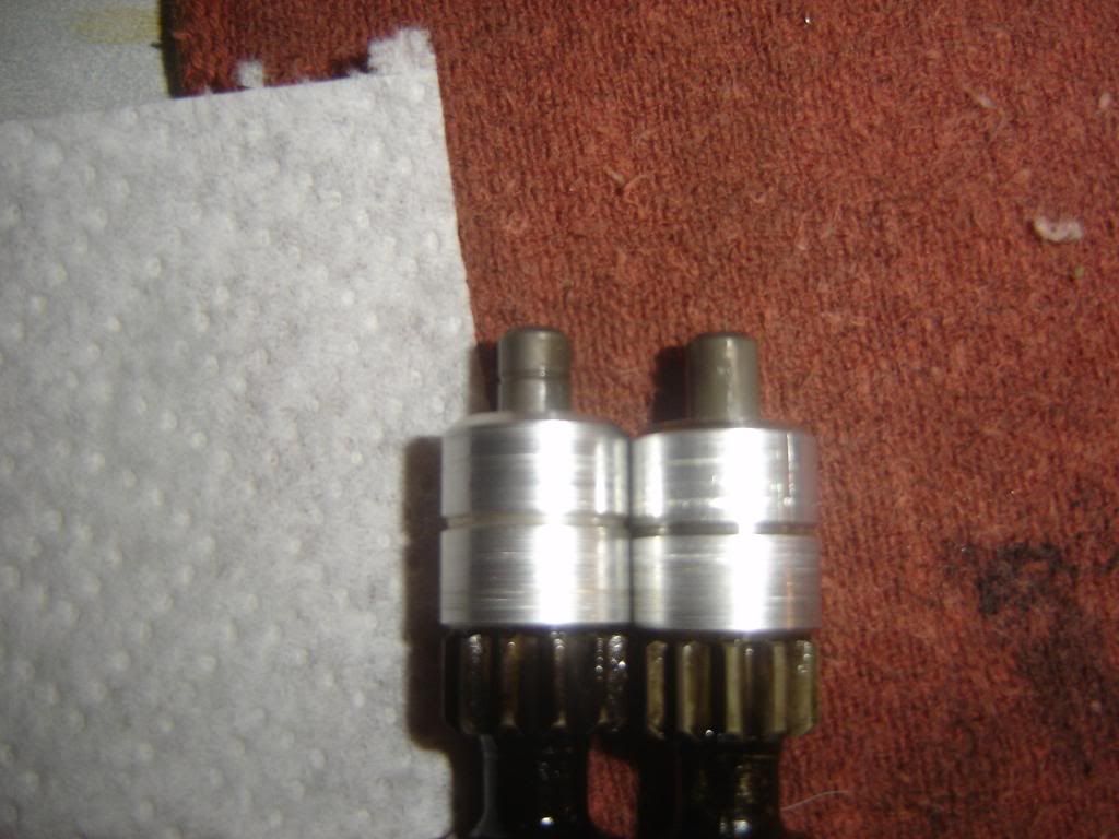
thses are the subvlaves, notice one has a ring/groove in the top of the shaft. that is the right subvalve, the one wilout the grove goes on the left side of the bike.
http://i222.photobucket.com/albums/dd18 ... nd2004.jpg
these are the subvalve shafts. notice one has a groove with an o-ring in it. that one also goes on the right side of the bike, the one without the o-ring goes on the left side of the bike
http://i222.photobucket.com/albums/dd18 ... nd2005.jpg
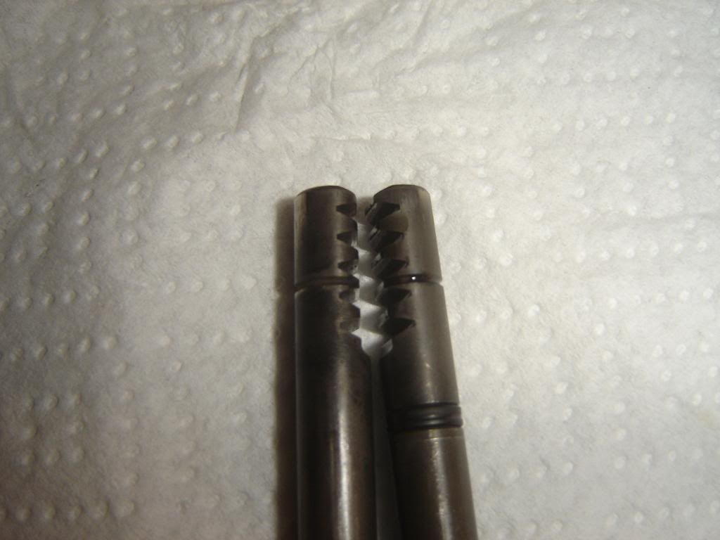
on the top of each subvalve is a timing mark. its a small area where 2 of the gear teeth are cut short. in the pic, it is the 2 teeth point up and to the right
http://i222.photobucket.com/albums/dd18 ... nd2006.jpg
also notice the timing mark grooves on the subvalve shafts, that correspond to the subvalve timing marks, this end goes into the cylinder first
http://i222.photobucket.com/albums/dd18 ... nd2008.jpg
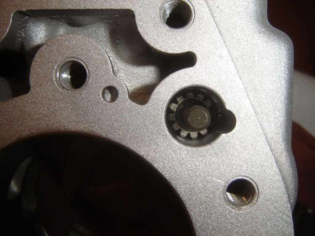
drop the subvlves in their holes without the aluminum bushings on top like so, make sure you oil the shaft with 2 stroke oil where the bushings rides and on the locating pin at the bottom of the valve
http://i222.photobucket.com/albums/dd18 ... nd2014.jpg
install the subvalve shafts, make sure you install them the correct way, oil the shafts as well. this one is on the wrong side, notice the teeth pointing up and not down.
http://i222.photobucket.com/albums/dd18 ... nd2013.jpg
now comes the tricky part. you must line up the timing marks on the subvlaves with the subvalve shafts. you will have to advace the subvalve, slide in the shaft and see if you got lucky, if not try again until you get it.
the top diagram in the pic
http://i222.photobucket.com/albums/dd18 ... nd2012.jpg
the actual thing
http://i222.photobucket.com/albums/dd18 ... nd2016.jpg
now you can put the aluminum bushings back on the subvalves in the cylinder, oil them.
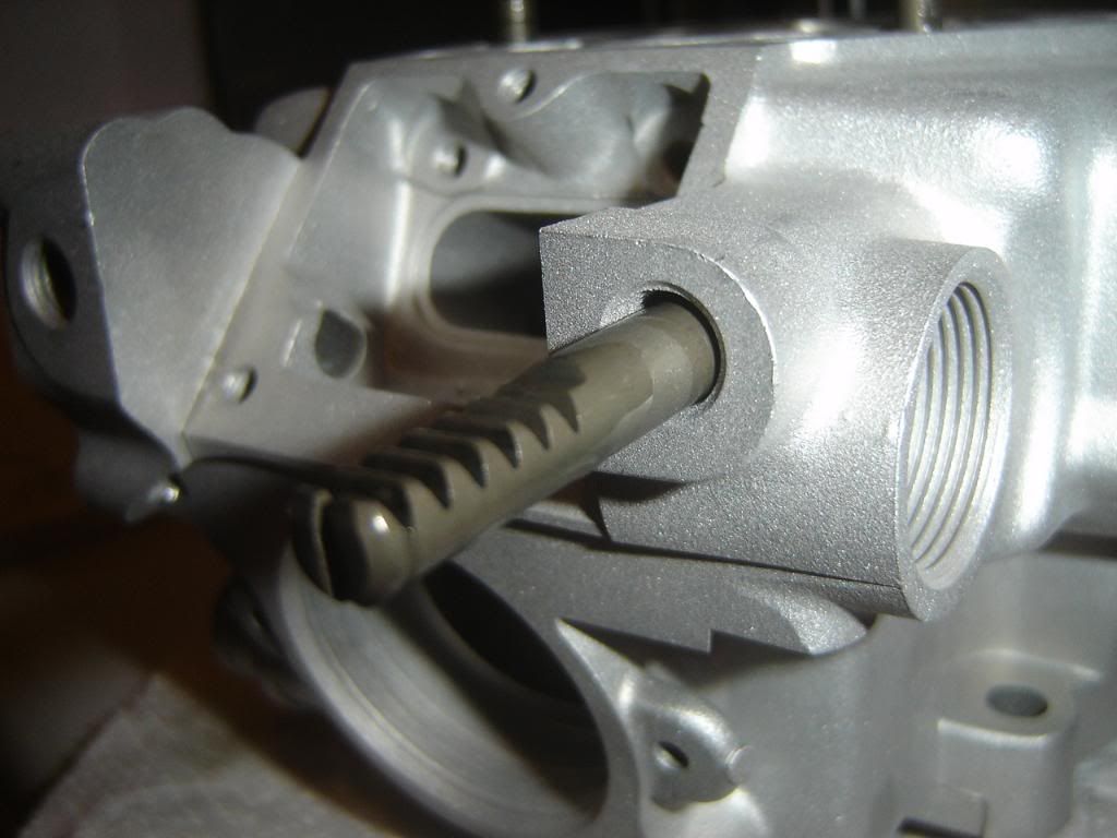
now you can install the main valve, drop it in its slot, tighted the 2 bolts to 52in.lbs. install the little rod with the flange on the left side (right side of the pic)
http://i222.photobucket.com/albums/dd18 ... nd2021.jpg
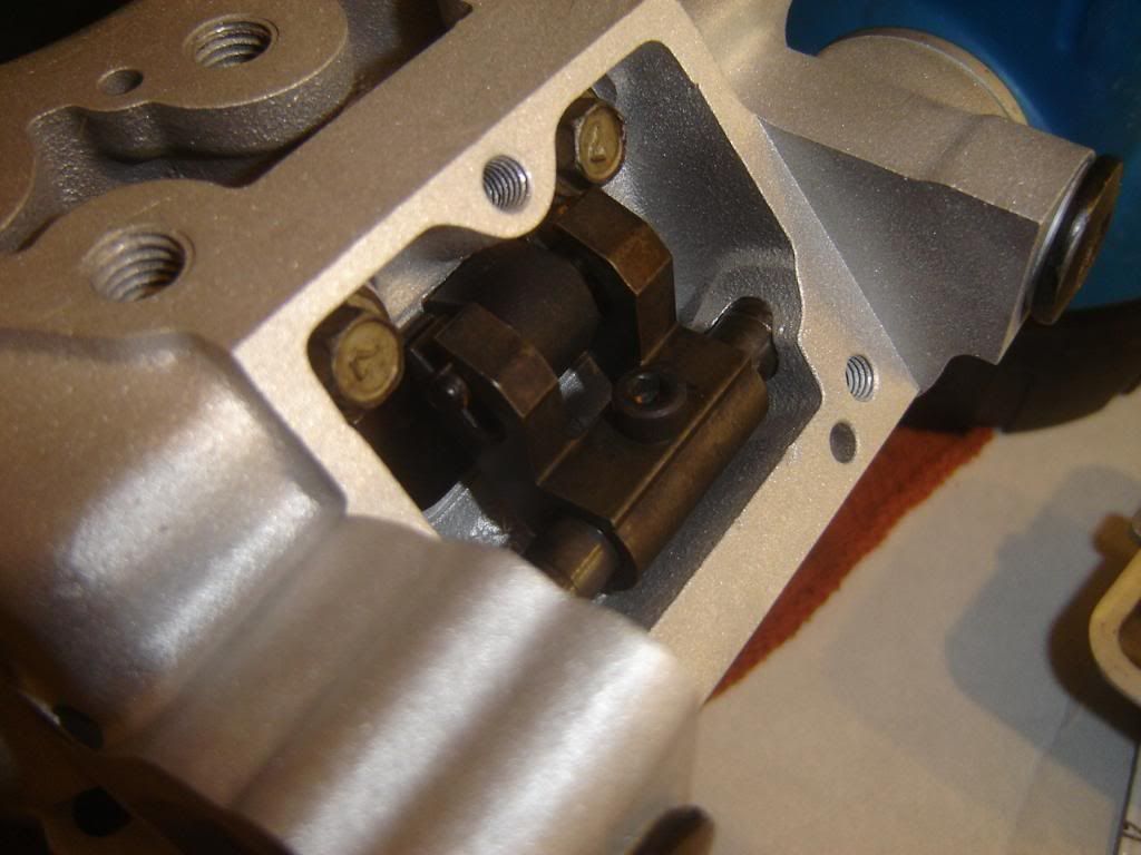
now you can install the main shaft. make sure both subvalve shafts are in the cylinder as far as they can go. this is the low rpm, or closed position. oil the seals in the cylnder and the main shaft. install the main valve arm on the main valve, and slide the main shaft through. make sure the dot on the gear lines up with the grove on the subvalve shaft on the right side. install the allen screw and torque to 35in. lbs
http://i222.photobucket.com/albums/dd18 ... nd2027.jpg
http://i222.photobucket.com/albums/dd18 ... nd2026.jpg
bottom diagram in the pic
http://i222.photobucket.com/albums/dd18 ... nd2012.jpg
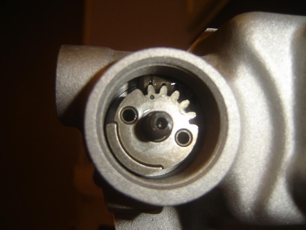
now you can install the gear on the left side, again make sure the dot lines up with the groove. install the nut and torque to 78in. lbs. it is very impotant to have the main shaft in the closed/low rpm position, and the left subvalve shaft in the closed/low rpm position when you tightn the main shaft nut. if you dont do this, the left subvalves will be out of time , since the main shaft and the left side gear are not keyed.
http://i222.photobucket.com/albums/dd18 ... nd2024.jpg
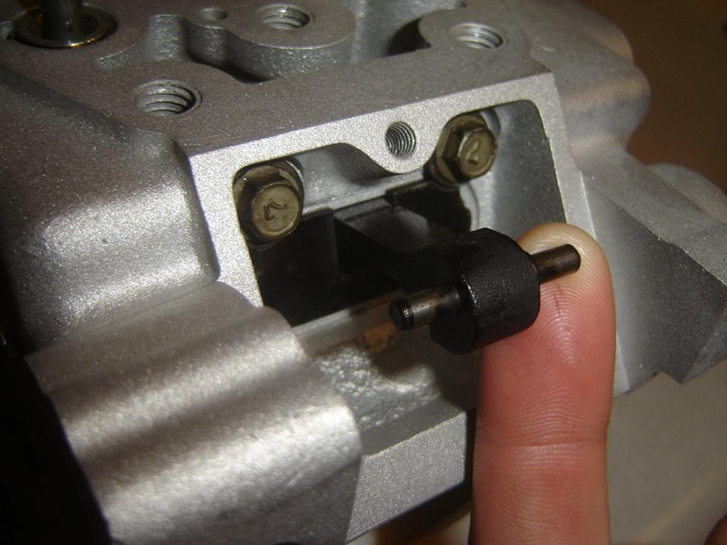
then install the little detent ball and screw thing, it goes just below the left side main shaft gear, torque to 69in. lbs
http://i222.photobucket.com/albums/dd18 ... nd2019.jpg
you kips is now assembled and timed correctly, install the main valve cover and resonator cover, torque both to 52in. lbs. install the subvalve shaft covers and torque to 13ft. lbs. install the left side plug hand tight with a screwdriver.
--------------------------------------------------------------------------------
hi_im_sean02-25-2009, 08:13 PM
Kips Operation:
Low RPM:
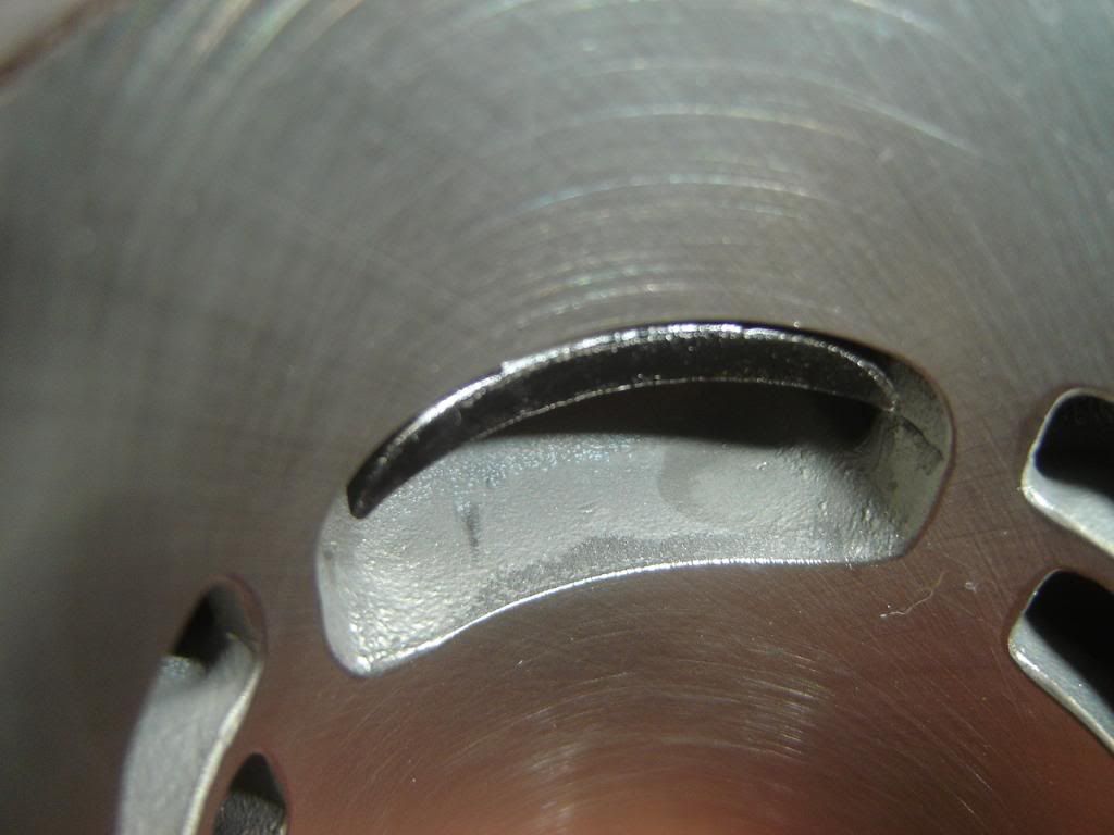
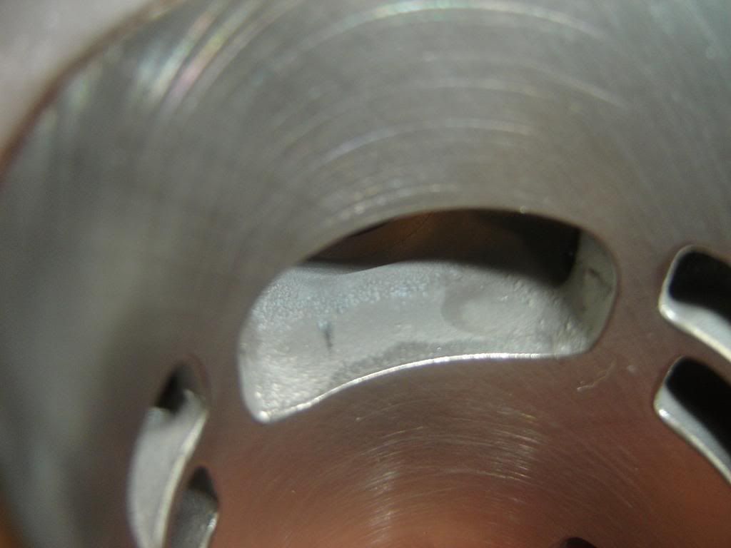
the main valve is down and effectivly retards the exhaust timing, both subvalves are closed which blocks off the 2 smaller exhaust sub ports
High RPM:
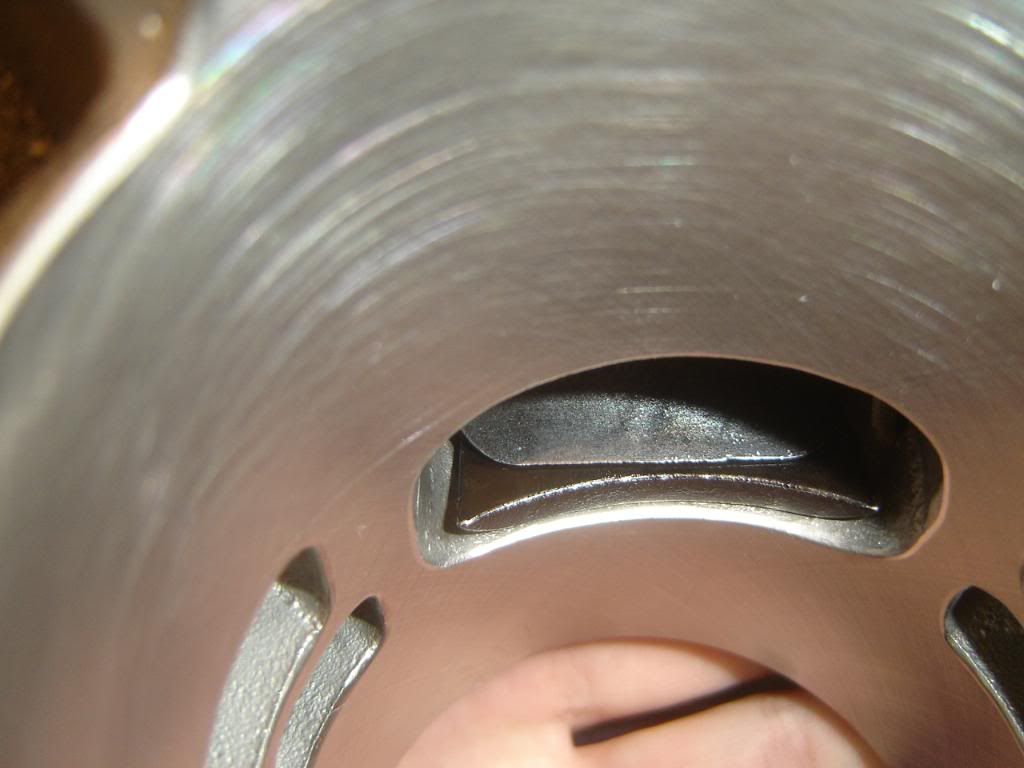
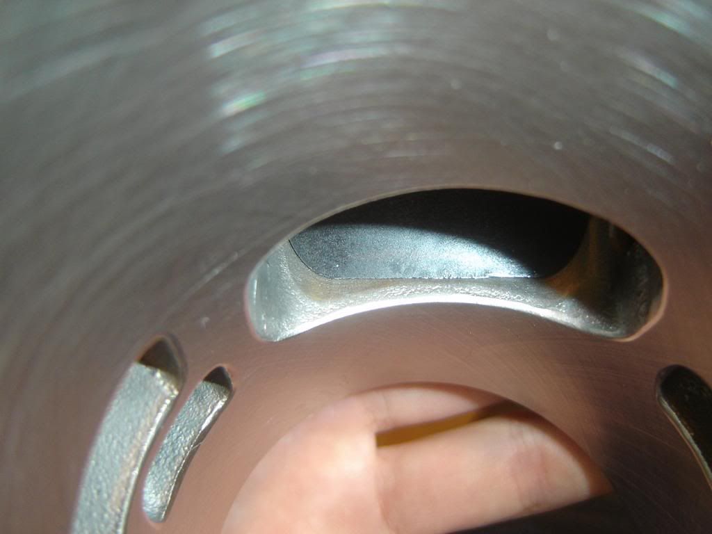
the main vlaves lifts up and retacts behind a plate, the port timing is advanced, the subvalves open and allow more exhaust flow by way of the 2 additional subports
main valve down
http://i222.photobucket.com/albums/dd18 ... nd2030.jpg
http://i222.photobucket.com/albums/dd18 ... nd2031.jpg
main valve up, and tucked away
http://i222.photobucket.com/albums/dd18 ... nd2029.jpg
http://i222.photobucket.com/albums/dd18 ... nd2032.jpg
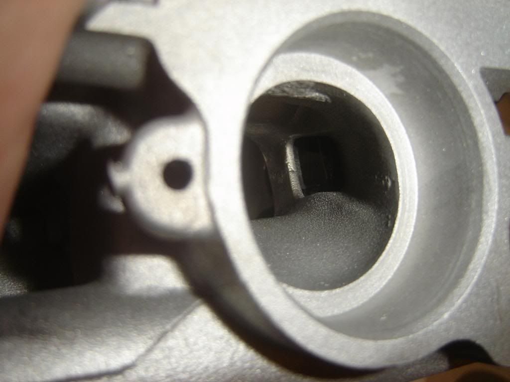
subvlave open (when main valve is up), couldnt get a good pic with it closed, the subvalve would just be turned until closed
http://i222.photobucket.com/albums/dd18 ... nd2018.jpg
Correct Kips Installation with pics
-
01twostrokingfun
- Member
- Posts: 43
- Joined: 04:46 pm May 02 2010
- Country:
- Location: Houston, Tx
- Contact:
-
skythrasher

- Supporting Member I

- Posts: 423
- Joined: 06:24 pm May 16 2007
- Country:
- Location: NW Arkansas
Re: Correct Kips Installation with pics
All that link clicking was giving me a headache. Isn't there a FATTY thread around here somewhere? 
>|QBB<[/url]
>|QBB<[/url]
01twostrokingfun wrote:Kips: Kawasaki Integrated Power-Valve System
disclaimer: i am not liable for what you do to your bike, or any dmage you cause from info here, and all that fun stuff, this is not a replacement for the manual, go get a real kawi manual
here are the parts that make up a kdx powervalve, the advancer shaft cover is missing from the pic, but everything else is there
this is the main valve
you can pull that pin out to separate the 2 peices for cleaning
subvalves: the sublaves and their shafts are different, and it does matter where they go. for simplicity, i will refer to everything as left and right side as you are sitting on the bike. the subvalves shafts will not work if they are swapped, the teeth on the shaft will be pointing in the wrong direction when you install them, and you will not be able to get the gears on. the subvlaves can be mixed up and the bike will run and nothing will get dmaged, but the powervalve will not work correclty, and you will loose power.
thses are the subvlaves, notice one has a ring/groove in the top of the shaft. that is the right subvalve, the one wilout the grove goes on the left side of the bike.
these are the subvalve shafts. notice one has a groove with an o-ring in it. that one also goes on the right side of the bike, the one without the o-ring goes on the left side of the bike
on the top of each subvalve is a timing mark. its a small area where 2 of the gear teeth are cut short. in the pic, it is the 2 teeth point up and to the right
also notice the timing mark grooves on the subvalve shafts, that correspond to the subvalve timing marks, this end goes into the cylinder first
drop the subvlves in their holes without the aluminum bushings on top like so, make sure you oil the shaft with 2 stroke oil where the bushings rides and on the locating pin at the bottom of the valve
install the subvalve shafts, make sure you install them the correct way, oil the shafts as well. this one is on the wrong side, notice the teeth pointing up and not down.
now comes the tricky part. you must line up the timing marks on the subvlaves with the subvalve shafts. you will have to advace the subvalve, slide in the shaft and see if you got lucky, if not try again until you get it.
the top diagram in the pic
the actual thing
now you can put the aluminum bushings back on the subvalves in the cylinder, oil them.
now you can install the main valve, drop it in its slot, tighted the 2 bolts to 52in.lbs. install the little rod with the flange on the left side (right side of the pic)
now you can install the main shaft. make sure both subvalve shafts are in the cylinder as far as they can go. this is the low rpm, or closed position. oil the seals in the cylnder and the main shaft. install the main valve arm on the main valve, and slide the main shaft through. make sure the dot on the gear lines up with the grove on the subvalve shaft on the right side. install the allen screw and torque to 35in. lbs
bottom diagram in the pic
now you can install the gear on the left side, again make sure the dot lines up with the groove. install the nut and torque to 78in. lbs. it is very impotant to have the main shaft in the closed/low rpm position, and the left subvalve shaft in the closed/low rpm position when you tightn the main shaft nut. if you dont do this, the left subvalves will be out of time , since the main shaft and the left side gear are not keyed.
then install the little detent ball and screw thing, it goes just below the left side main shaft gear, torque to 69in. lbs
you kips is now assembled and timed correctly, install the main valve cover and resonator cover, torque both to 52in. lbs. install the subvalve shaft covers and torque to 13ft. lbs. install the left side plug hand tight with a screwdriver.
--------------------------------------------------------------------------------
hi_im_sean02-25-2009, 08:13 PM
Kips Operation:
Low RPM:
the main valve is down and effectivly retards the exhaust timing, both subvalves are closed which blocks off the 2 smaller exhaust sub ports
High RPM:
the main vlaves lifts up and retacts behind a plate, the port timing is advanced, the subvalves open and allow more exhaust flow by way of the 2 additional subports
main valve down
main valve up, and tucked away
subvlave open (when main valve is up), couldnt get a good pic with it closed, the subvalve would just be turned until closed


-
kdxmaniac

- Supporting Member
- Posts: 595
- Joined: 09:01 pm May 24 2010
- Country:
Re: Correct Kips Installation with pics
quote="skythrasher"]All that link clicking was giving me a headache. Isn't there a FATTY thread around here somewhere?
 there i go laughing again!!
my bikes
-------------
96 ktm 300
96 XR400R
07 hayabusa
77 kz 1000
85 goldwing 1200
02 BIG DOG PITBULL
gone but not forgotten
96 kdx 200
98 ktm 380 "because it dang near killed me!"
97 ktm 360
96 ktm 250
93 wr 250
94 dr 350s
93 kx 250
07 gsxr 1000
99 bandit 1200
-------------
96 ktm 300
96 XR400R
07 hayabusa
77 kz 1000
85 goldwing 1200
02 BIG DOG PITBULL
gone but not forgotten
96 kdx 200
98 ktm 380 "because it dang near killed me!"
97 ktm 360
96 ktm 250
93 wr 250
94 dr 350s
93 kx 250
07 gsxr 1000
99 bandit 1200