Page 1 of 1
trail tech endurance computer
Posted: 12:58 am Jul 19 2008
by jaydollar
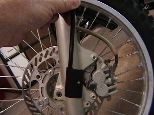
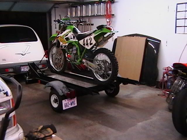
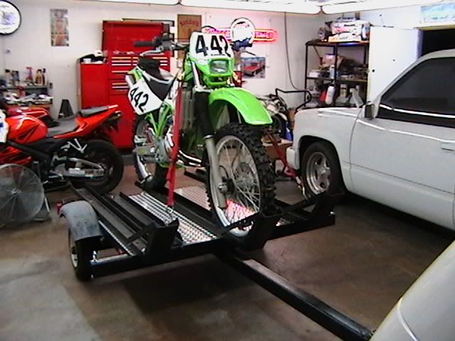
bought off of estray!!! part #500-20 for kdx 200/220 i shoe horned pick up end between fork and caliper bracket to line up with supplied magnetic rotor bolt and instructions say 1/2 inch max distance, i am lucky to get a red "c" hair between them unless i remove the extra magnetic disc it came with.this is from top of bike looking down left fork tube.i can move it up and down approx. 1/4 inch or so to line up the rotor bolt between the length of the plastic pick up coil wich is approx. 1 inch long. should i put it in the middle of the plastic top to bottom, and chunk the extra disc.any help will be appreciated and i will post close ups when i get er dunn !!!
Posted: 12:00 pm Jul 20 2008
by canyncarvr
No one has a trail tech installed to answer this question?
Surely someone does!

Posted: 02:17 pm Jul 20 2008
by AZRickD
I know there's a question in there somewhere (question marks help). I couple of photos would go a lot farther than a hastily typed post, anyway.
I have a Trail Tech Vapor on the KDX with that plastic pickup that screws on sideways-like to the caliper. I'm also in the process of figuring out (in my Gas Gas) how to make my Endurance pickup happy with the magnet. The Gas Gas rotor bolts (where the magnabolt goes) is off-arc of the pickup by 1.25-inches which doesn't send a signal to the unit. I'm trying to decide whether to fab a bracket or to drill a hole in one of the all-too-thin Gasser rotor rays (allowing only 3/16" on either side of the required 3/8" magnet hole).
Sorry for the almost hi-jack.
Again, a photo would be nice, like this'n, only bigger:
Posted: 02:18 pm Jul 20 2008
by AZRickD
Ooops
Re: trail tech endurance computer
Posted: 08:24 pm Jul 22 2008
by recurve


jaydollar wrote:bought off of estray!!! part #500-20 for kdx 200/220 i shoe horned pick up end between fork and caliper bracket to line up with supplied magnetic rotor bolt and instructions say 1/2 inch max distance, i am lucky to get a red "c" hair between them unless i remove the extra magnetic disc it came with.this is from top of bike looking down left fork tube.i can move it up and down approx. 1/4 inch or so to line up the rotor bolt between the length of the plastic pick up coil wich is approx. 1 inch long. should i put it in the middle of the plastic top to bottom, and chunk the extra disc.any help will be appreciated and i will post close ups when i get er dunn !!!
Not quite sure what you are describing. The TrailTech instructions are right on. They can be found on the TrailTech website if your computer didn't come with the instruction booklet. The magnetic bolt replaces one of the caliper bolts. The plastic pickup requires a single screw hole drilled into the brake caliper mount (not the caliper, the mount bracket that the caliper bolts too). The drawing in the instructions shows the placement of the pickup in relation to the magnetic screw. I'd post photos but the bike is in garage and I'm not.
Posted: 10:40 am Jul 23 2008
by canyncarvr
Re: 'They can be found on the TrailTech website if your computer didn't come with the instruction booklet.'
Good point!
This pic comes from their site:

..with this text:
Trail Tech wrote:
The brake caliper must be removed to install the
sensor, in most cases. Position the sensor on the
brake caliper as shown. With the sensor held down
firmly in the correct position on the caliper, insert an
ink pen through the mounting hole on the sensor
to mark for the drill location. Remove the sensor
and drill a 1/8” hole through caliper mount. Use
a sharp drill bit! Attach the sensor to the caliper
mount with the screw provided. This is a selftapping
screw - the hole size must be 1/8”.
If your wheel isn't centered in the forks (a process done any time the front wheel is put on), that could have something to do with it.
I don't suppose the term 'shoe horned' would be used if the caliper was removed as noted?
How 'bout this:
Trail Tech wrote:Do not mount so that the magnet passes the middle section of the sensor. Either the sensor will not register at all; or the sensor will register twice, causing a “double trigger” effect (computer displays twice the true speed.)
The graphic associated with THAT statment shows the slug a good bit away from the pickup.

Maybe yours is mounted in such as way as to make the slug pass directly past the pickup?
That's not right, by their description.
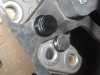
Posted: 01:02 pm Jul 23 2008
by jaydollar
Posted: 01:50 pm Jul 23 2008
by canyncarvr
You're there...I'm not...but...
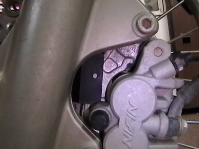
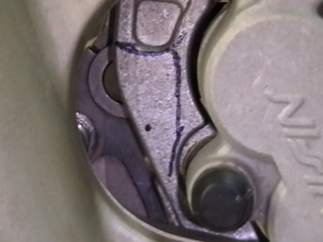
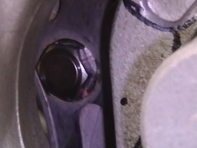
Where the hole is in the pickup bracket doesn't appear to match where the dot is on the caliper mount. It looks to be pretty 'thin' (close to the edge) where the dot is.
The orientation indicated in the TrailTech pic doesn't appear to match where you're holding/drawing indicates.
OK...I'll quit with the vagaries. Where THEY say to put it is NOT the same as where you marked yours. It won't fit as they say? Maybe not. Wouldn't be the first time 'instructions' were bogus.
IF you don't put it where they say it needs to be AND get spurious double tics..the whole thing (job, time, computer) will be worthless.
What's wrong with the self-tappers?
Posted: 11:45 pm Jul 23 2008
by jaydollar
thanks again carvr. i think the 1/2 max is for radial and axial run out.the road atlas of an instruction sheet i got resembled highroglifics from the romans.i did re-position for a better fit to get more meat between the edge of the caliper bracket and the pickup. this also moved the pickup higher, to put it in the arc of the magnet more like the pic you sent with the blue lines. after dial in as per instructons, with the roll out on the front wheel,i had my neighber pace me down the street with his caddy. the one with old digital speedo, the blue one from the late 80's, and i was dead nut's at 20, 30, and 40 mph. any faster and i would have thrown a vaper trail !!! as for the self tapper's, they always seem to strip out the head before they get all the way in. probably from drilling to small of a pilot hole.i know to drill a #36 (.106) for a 6-32 tapped hole. good night for now and good luck for ski, j$
Posted: 12:33 am Jul 24 2008
by canyncarvr
On the self tap screws..run them in the first time just as you would a tap. 1/2 turn in, 1/4 turn out sort of thing.
As long as you're not using a #1 phillips on a #2 screw head..or some other mess like a Reed and Prince tipped driver, you shouldn't have any trouble with the head giving out.
(Reed and Prince looks like a Phillips...but it ain't Jis like it)
..thass'a joke, son.....
Glad you got it sorted out! Good job! It's a good thing when things work.