Squish Velocity info
Posted: 12:39 am Apr 19 2016
So far most of what I’ve read about squish bands is that reducing the squish area increases power but if you reduce it too much it will cause detonation (by reducing the insulating fuel mixture between the head and the piston). The most commonly promoted squish velocity has been 28m/sec. But now I found a research paper studying the various effects of different squish velocities that is rather eye-opening. I didn’t know that too much velocity actually slows down the combustion time by overtly dispersing the flame kernel. Also I had no idea that squish affects ignition timing requirements and loads on the rod and crank bearings. This data was obtained from a 2 stroke engine similar in dimensions to the KDX200 in that it has 199cc, 70mm bore, 184 duration exhaust, 126 duration transfers. The most alarming of this new (to me) information is the excess bearing loads that can result. At 7000 RPM the crankpin load with the 15.2m/s head became 2.75 times that of the 24.4m/s head. No one likes replacing bearings so maybe we all should take a close look at this before we decide on any change to the KDX head. I would like to hear of peoples experience with mods but unfortunately most people are disqualified from the start because they did more to the bike than just change the head configuration. (like a carb change or they also increased compression) Has anyone experienced a shortening of bearing life due to a head mod? Has anyone experienced some engine roughness (possible detonation evidenced by spots of piston erosion)? I personally think the biggest advantage of having a squish band is the cooling effect on the piston and rings. It keeps the outer edge of the piston from getting as hot, and it shoots a cooling blast of fuel mixture across the top of the piston which then goes upward to push the flame "ball" outward along the surface of the head and away from the piston. All of the following is from the research paper. The D head is without a squish band.
Squish Velocity in the Combustion Chamber of a 2-Stroke Cycle Engine
Avraham Ziv, Engineering Div., McCulloch Corp.
Four cylinder heads with different combustion chamber dimensions were built to test the effect of various squish velocities on a number of engine parameters. All four heads had the same compression ratio, spark plug location, and squish height. The only variables were the combustion chamber dimensions that resulted in the estimated squish velocities.
Max Values at 6000 RPM
------ squish velocity ---------------------- optimum ------- pressure rise
head - meters/sec* --- peak psi ---- peak HP -- timing BTDC ---- psi/degree
A ---- 33.5 ----------- 725 ------- 16.34 ----- 27* ------------ 31
B ---- 24.4 ----------- 780 ------- 16.34 ----- 21* ------------ 33
C ---- 15.2 ----------- 810 ------- 16.84 ----- 19* ------------ 21
D ---- 0 -------------- 705 ------- 16.44 ----- 23* ------------ 26
* at 18 degrees BTDC
-------- horsepower
RPM- head A--- B ---- C ----- D
6000 - 16.34 - 16.34 - 16.84 - 16.44
6500 - 17.99 - 18.04 - 18.51 - 18.18
7000 - 19.29 - 19.40 - 19.60 - 19.49
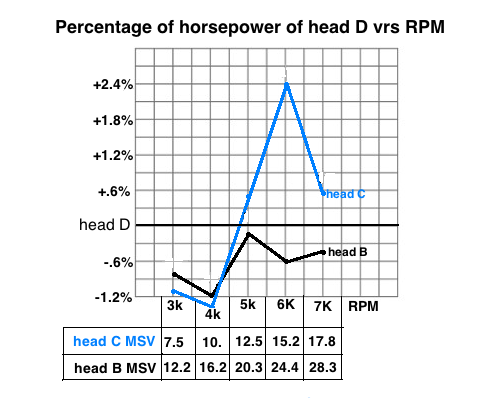
It appears that head C shows slightly better power than the other heads, in the range of 6000-7000 rpm. [The power of head C is significantly better than the A and B heads at 6000 and 6500 rpm (3%) and maintains a slight advantage at 7000 rpm.]
It is an accepted theory that increased turbulence increases the burning rate (4); hence, one would expect to find the optimum spark timing to retard as the degree of turbulence increases. Fig. 13 indicates that the highest turbulence head (A) requires the most spark advance (27 deg BTDC). The spark timing retards as the degree of turbulence is reduced, coming to the most retard point with head C. It appears that, when the degree of turbulence increased beyond a certain point it begins to interfere with the formation of the initial nucleus of flame; hence, the high-turbulence head will require additional time to obtain optimum combustion.
The rate of pressure rise and the maximum cylinder pressure will affect the loads exerted on engine structural components (wrist pin, connecting rod, crankshaft, bearings) and degree of smoothness of engine running. A very high rate of pressure will result in what is known as "engine roughness." Ricardo (2) set the threshold of the rate of pressure rise to start engine roughness to be between 30-35 psi/deg. The rate of pressure rise can be controlled by the shape of the combustion chamber and by the degree of turbulence. Using 30psi/deg for the threshold to start engine roughness it appears that engines with head C or D will run smoother than with head A or B.
Gas pressure, inertia forces, and centrifugal forces induce bending and torsional stresses in the crankshaft. In this discussion, only bending stresses will be considered, and, in particular, those which are directly resulted from gas pressure. These loads are mainly a function of two variables: maximum combustion pressure and crank angle at which maximum pressure occurs. Crankshaft bending loads can be divided into: stresses in the plane of the throws, and stresses in the plane transverse to the throws. These are illustrated in Fig. 24. The improvement gained by lowering the rate of pressure rise in a lower squish combustion chamber [head C] is offset by the increase in crankshaft bending loads.
Tangential Force On Crankpin, lbs
RPM -- head A -- B ----- C ----- D
4000 -- 341 -- 1142 -- 2077 -- 2053
5000 -- 681 -- 1223 -- 2405 -- 1964
6000 -- 691 -- 956 --- 2225 -- 1780
7000 -- 167 -- 950 --- 2621 -- 1254
Squish Velocity in the Combustion Chamber of a 2-Stroke Cycle Engine
Avraham Ziv, Engineering Div., McCulloch Corp.
Four cylinder heads with different combustion chamber dimensions were built to test the effect of various squish velocities on a number of engine parameters. All four heads had the same compression ratio, spark plug location, and squish height. The only variables were the combustion chamber dimensions that resulted in the estimated squish velocities.
Max Values at 6000 RPM
------ squish velocity ---------------------- optimum ------- pressure rise
head - meters/sec* --- peak psi ---- peak HP -- timing BTDC ---- psi/degree
A ---- 33.5 ----------- 725 ------- 16.34 ----- 27* ------------ 31
B ---- 24.4 ----------- 780 ------- 16.34 ----- 21* ------------ 33
C ---- 15.2 ----------- 810 ------- 16.84 ----- 19* ------------ 21
D ---- 0 -------------- 705 ------- 16.44 ----- 23* ------------ 26
* at 18 degrees BTDC
-------- horsepower
RPM- head A--- B ---- C ----- D
6000 - 16.34 - 16.34 - 16.84 - 16.44
6500 - 17.99 - 18.04 - 18.51 - 18.18
7000 - 19.29 - 19.40 - 19.60 - 19.49
It appears that head C shows slightly better power than the other heads, in the range of 6000-7000 rpm. [The power of head C is significantly better than the A and B heads at 6000 and 6500 rpm (3%) and maintains a slight advantage at 7000 rpm.]
It is an accepted theory that increased turbulence increases the burning rate (4); hence, one would expect to find the optimum spark timing to retard as the degree of turbulence increases. Fig. 13 indicates that the highest turbulence head (A) requires the most spark advance (27 deg BTDC). The spark timing retards as the degree of turbulence is reduced, coming to the most retard point with head C. It appears that, when the degree of turbulence increased beyond a certain point it begins to interfere with the formation of the initial nucleus of flame; hence, the high-turbulence head will require additional time to obtain optimum combustion.
The rate of pressure rise and the maximum cylinder pressure will affect the loads exerted on engine structural components (wrist pin, connecting rod, crankshaft, bearings) and degree of smoothness of engine running. A very high rate of pressure will result in what is known as "engine roughness." Ricardo (2) set the threshold of the rate of pressure rise to start engine roughness to be between 30-35 psi/deg. The rate of pressure rise can be controlled by the shape of the combustion chamber and by the degree of turbulence. Using 30psi/deg for the threshold to start engine roughness it appears that engines with head C or D will run smoother than with head A or B.
Gas pressure, inertia forces, and centrifugal forces induce bending and torsional stresses in the crankshaft. In this discussion, only bending stresses will be considered, and, in particular, those which are directly resulted from gas pressure. These loads are mainly a function of two variables: maximum combustion pressure and crank angle at which maximum pressure occurs. Crankshaft bending loads can be divided into: stresses in the plane of the throws, and stresses in the plane transverse to the throws. These are illustrated in Fig. 24. The improvement gained by lowering the rate of pressure rise in a lower squish combustion chamber [head C] is offset by the increase in crankshaft bending loads.
Tangential Force On Crankpin, lbs
RPM -- head A -- B ----- C ----- D
4000 -- 341 -- 1142 -- 2077 -- 2053
5000 -- 681 -- 1223 -- 2405 -- 1964
6000 -- 691 -- 956 --- 2225 -- 1780
7000 -- 167 -- 950 --- 2621 -- 1254