KDX Lighting Stator Rewind How-To
-
SS109

- KDXRider.net

- Posts: 5796
- Joined: 05:11 am Aug 23 2009
- Country: USA
- Location: Tucson, AZ, USA
- Contact:
I'm eagerly awaiting the new test data!
Youtube Channel: WildAzzRacing
AZ State Parks & Trails OHV Ambassador - Trail Riders of Southern AZ
Current KDX: '98 KDX220
Old KDX: '90 KDX200 -White/Blue
'11 GasGas EC250R
AZ State Parks & Trails OHV Ambassador - Trail Riders of Southern AZ
Current KDX: '98 KDX220
Old KDX: '90 KDX200 -White/Blue
'11 GasGas EC250R
-
Slick_Nick

- Supporting Member
- Posts: 1675
- Joined: 10:06 pm Oct 22 2009
- Country: Canada
- Location: Calgary, Alberta
- Contact:
-
gtoron
- Member
- Posts: 173
- Joined: 09:18 am Apr 13 2006
- Country:
- Location: Long Island NY
Great pics and video.
Three questions for you. I heard this adds some performance to the bottom end? Is that true?
Where did you get the wire?
Also you said there is 200 yards of wire which is 600 feet...is that a pound of wire as it seems places sell in 1/4 pound 1/2 pound 1 pound and ten pound spools.
Thanks for the info
-
chkdx
- Supporting Member I

- Posts: 132
- Joined: 09:31 pm Oct 02 2009
- Country:
- Location: Carson City, NV
Well, I actually am an electrical engineer, so I thought I'd throw a thought in here. Nick, your first test was in fact incorrect. You measured open circuit voltage and short circuit current separately, so they cannot be multiplied together to obtain the correct wattage. You do, indeed, have to measure them simultaneously to get the real wattage.
Think of it like a fuel pump. If you measure the pump's output pressure with the outlet blocked by the pressure gage, the reading will be the max pressure the pump can put out. If you then check the flow by just running the pump output into a bucket, the pump is putting up plenty of flow, but no pressure, so it's incorrect to say "This pump puts out 30 gallons per hour at 15 PSI" when the pump's max pressure was 15 PSI.
Now you brought up the regulator. Let's add a pressure regulator to the fuel pump, and set it at 12.5 PSI (kinda like the 12.5 volts of a voltage regulator). If you then run the output of the regulator into a bucket, the output pressure is still zero, not 12.5 PSI, so it's still not a valid test. What you have to do is restrict the outlet flow (with, say a valve) until the pressure before the valve just barely drops just below 12.5 PSI, say to 12 PSI then measure the flow out of the valve. You can then say "This pump flows X gallons per hour at 12 PSI."
Similarly, the right way to do your electrical test is to restrict the current flow through the ammeter, with resistors or extra bulbs, until the voltage seen by those resistors or bulbs is, say, 12 Volts, then note the amperage. You can then say "The output is X amps at 12 volts, therefore the wattage is X amps times 12 volts." Note: the resistors or bulbs are put in series with the ammeter for this test.
You are correct that trying to measure output at much above 12 volts won't work as the regulator will shunt current to ground to maintain around 12.5 volts. However, you may well find (probably WILL find) that if you rev the engine up to say 5000 rpm during the test, you'll have to reduce the test resistance to keep the voltage at 12 Volts, so more current will flow, and available wattage will therefore be increased at higher rpm.
Clear as mud? Hope it helps! I'll be watching this closely as I'm going to try rewinding my stator as well.
-
Slick_Nick
- Supporting Member
- Posts: 1675
- Joined: 10:06 pm Oct 22 2009
- Country: Canada
- Location: Calgary, Alberta
- Contact:
-
TWMOODY

- Gold Member

- Posts: 752
- Joined: 08:10 pm Dec 01 2006
- Country:
- Location: Southeast , Michigan
Exactly !chkdx wrote:Well, I actually am an electrical engineer, so I thought I'd throw a thought in here. Nick, your first test was in fact incorrect. You measured open circuit voltage and short circuit current separately, so they cannot be multiplied together to obtain the correct wattage. You do, indeed, have to measure them simultaneously to get the real wattage.
Think of it like a fuel pump. If you measure the pump's output pressure with the outlet blocked by the pressure gage, the reading will be the max pressure the pump can put out. If you then check the flow by just running the pump output into a bucket, the pump is putting up plenty of flow, but no pressure, so it's incorrect to say "This pump puts out 30 gallons per hour at 15 PSI" when the pump's max pressure was 15 PSI.
Now you brought up the regulator. Let's add a pressure regulator to the fuel pump, and set it at 12.5 PSI (kinda like the 12.5 volts of a voltage regulator). If you then run the output of the regulator into a bucket, the output pressure is still zero, not 12.5 PSI, so it's still not a valid test. What you have to do is restrict the outlet flow (with, say a valve) until the pressure before the valve just barely drops just below 12.5 PSI, say to 12 PSI then measure the flow out of the valve. You can then say "This pump flows X gallons per hour at 12 PSI."
Similarly, the right way to do your electrical test is to restrict the current flow through the ammeter, with resistors or extra bulbs, until the voltage seen by those resistors or bulbs is, say, 12 Volts, then note the amperage. You can then say "The output is X amps at 12 volts, therefore the wattage is X amps times 12 volts." Note: the resistors or bulbs are put in series with the ammeter for this test.
You are correct that trying to measure output at much above 12 volts won't work as the regulator will shunt current to ground to maintain around 12.5 volts. However, you may well find (probably WILL find) that if you rev the engine up to say 5000 rpm during the test, you'll have to reduce the test resistance to keep the voltage at 12 Volts, so more current will flow, and available wattage will therefore be increased at higher rpm.
Clear as mud? Hope it helps! I'll be watching this closely as I'm going to try rewinding my stator as well.
-
Slick_Nick
- Supporting Member
- Posts: 1675
- Joined: 10:06 pm Oct 22 2009
- Country: Canada
- Location: Calgary, Alberta
- Contact:
Well, the results are in! Wasn't 100W, but it wasn't far off!
I went through a very systematic process today, and here are my findings:
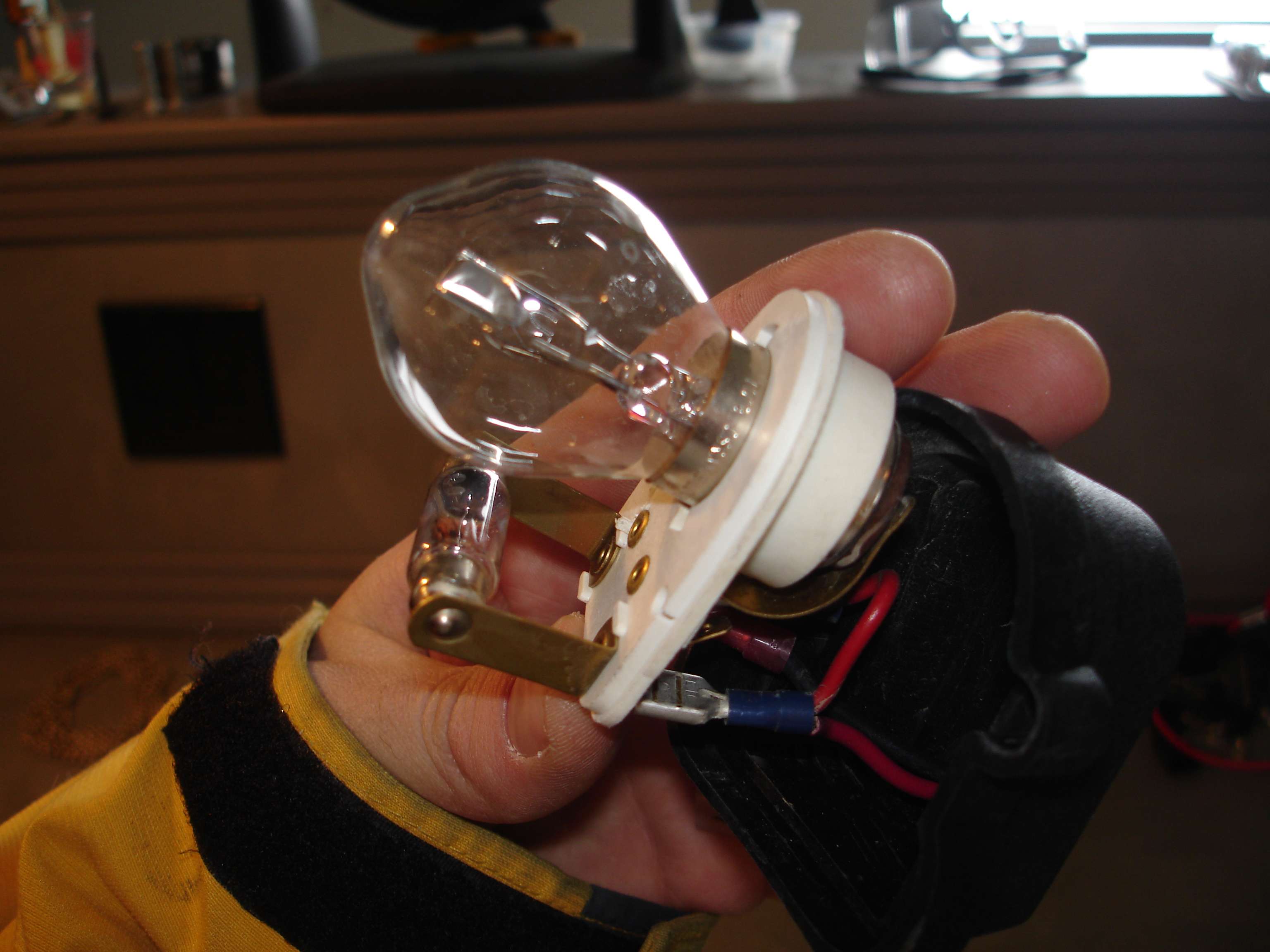
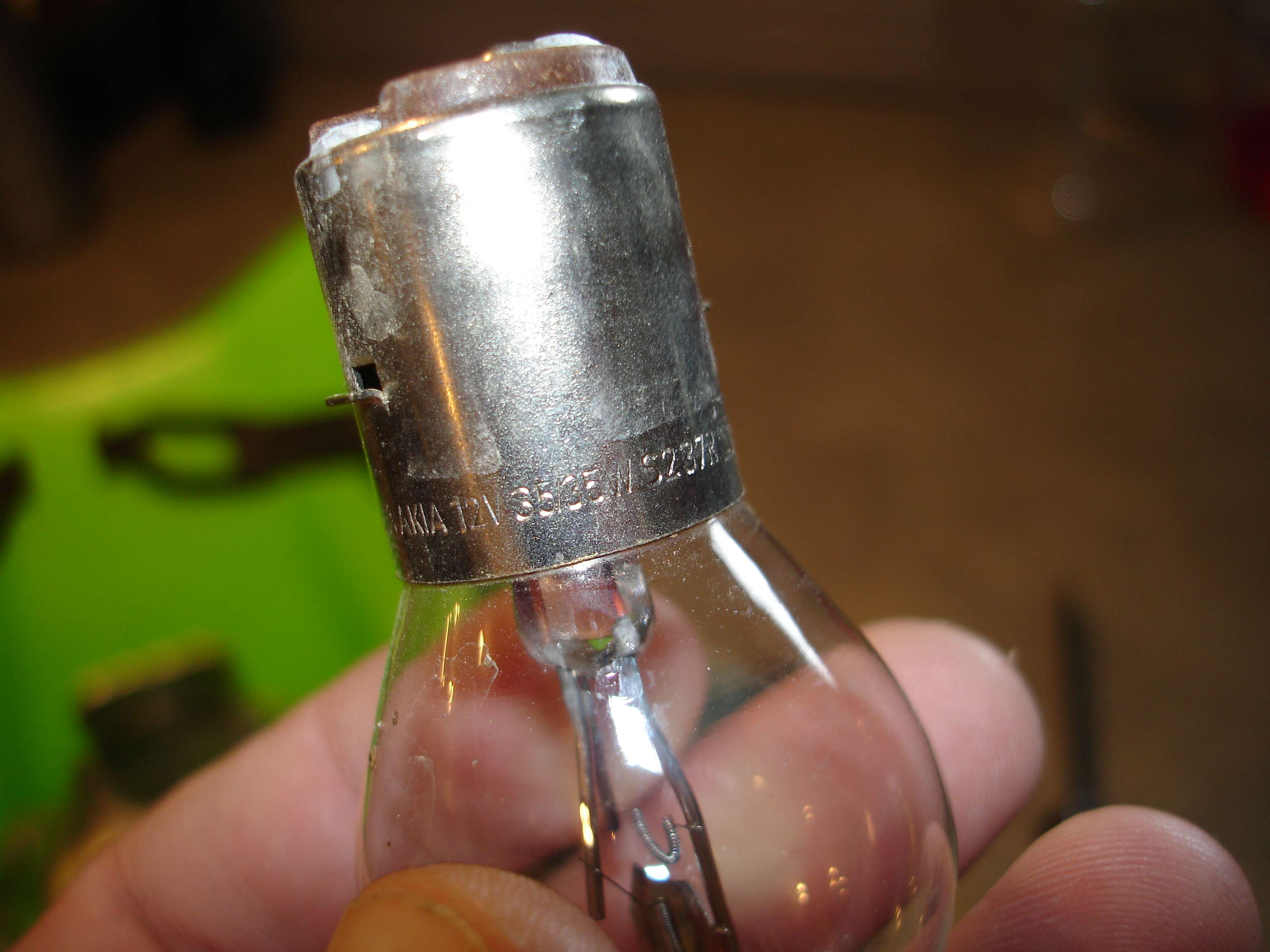
First off, I started out by looking at my "stock" headlight, to see if there was any explanation for the extra current draw I was seeing before. Turns out, it was NOT a stock headlight, but a UFO unit. The way it was wired, was such that BOTH "high and low beam" fillaments were being used, at 35W each, for a total headlight draw of 70W. Note the lower fuse type bulb is not used, I'm talking about both fillaments in the main headlamp itself.
Onto the actual testing:
**All photos were taken at idle unless otherwise noted***
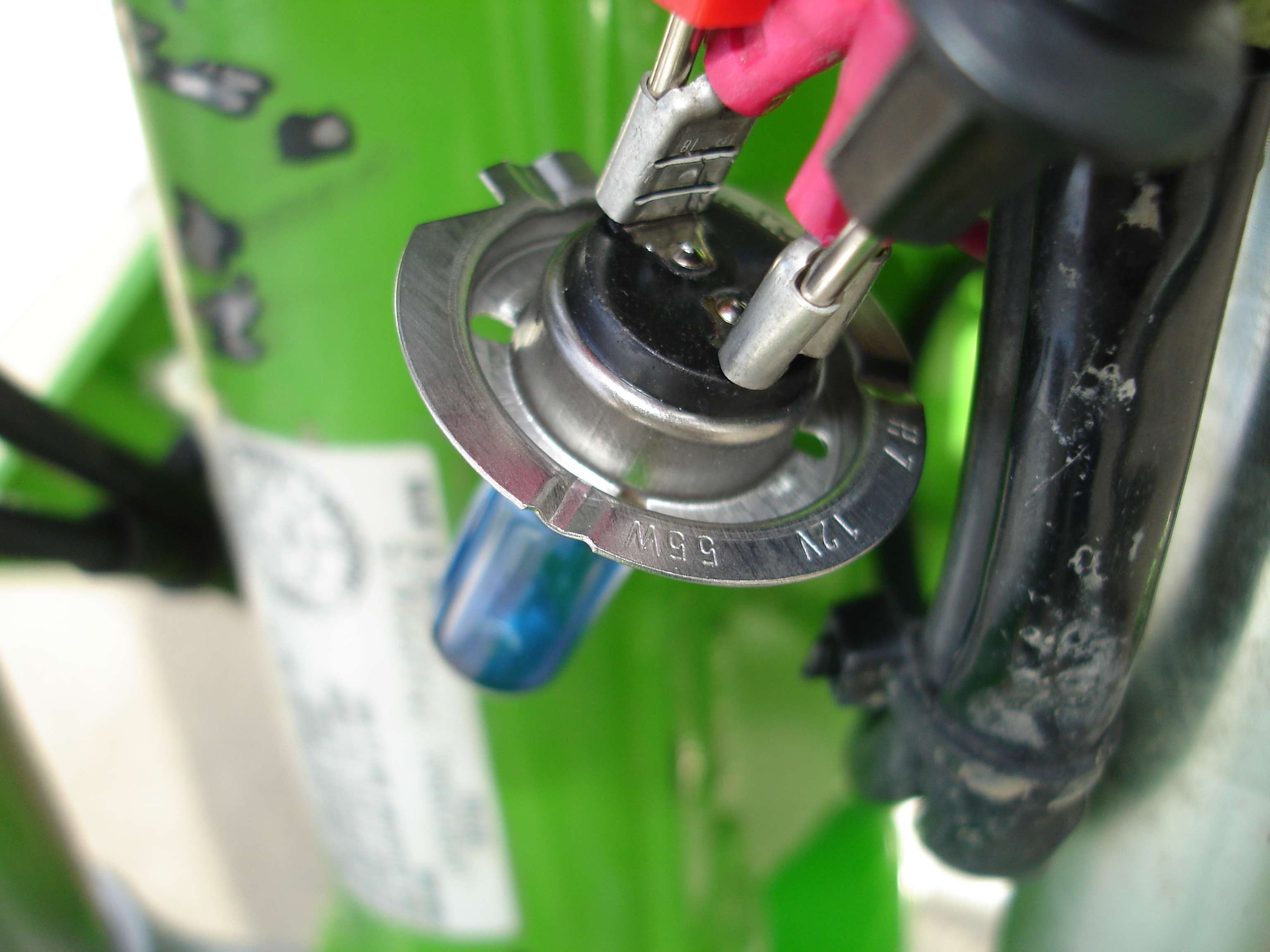
Knowing that my previous headlight was capable of pulling 70W, I knew 1 H7 bulb would be no problem @ 55W. I decided to try it anyway.
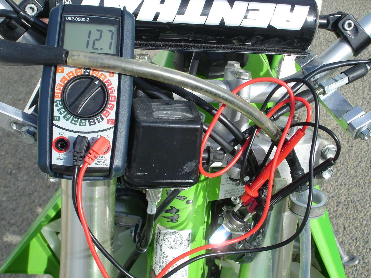
The test setup is as follows:
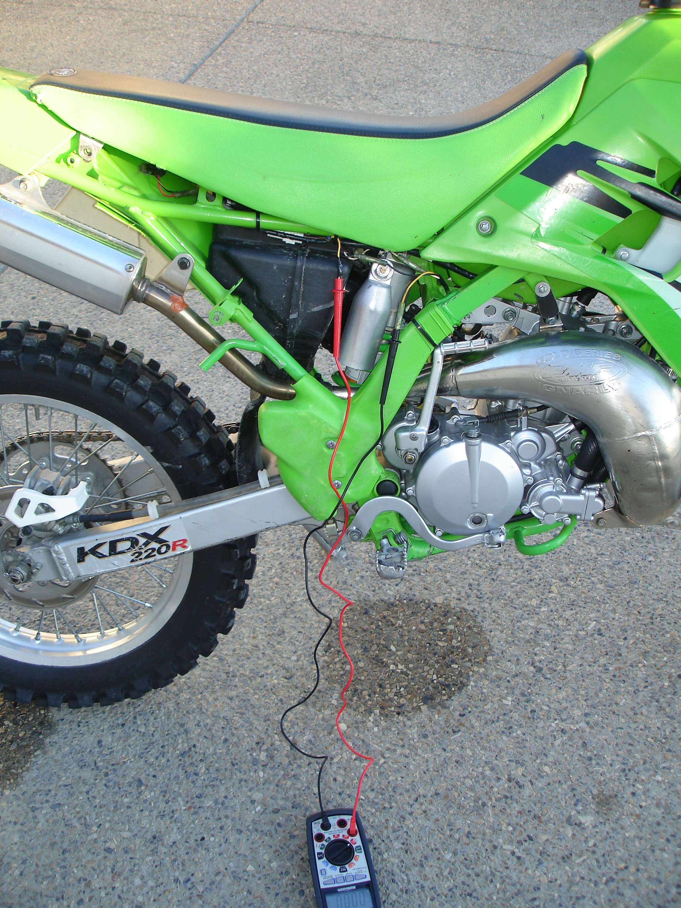
An AC multimeter setup to show AC current, wired in-line with the yellow wire coming off the lighting coil. This is the raw output right from the stator.
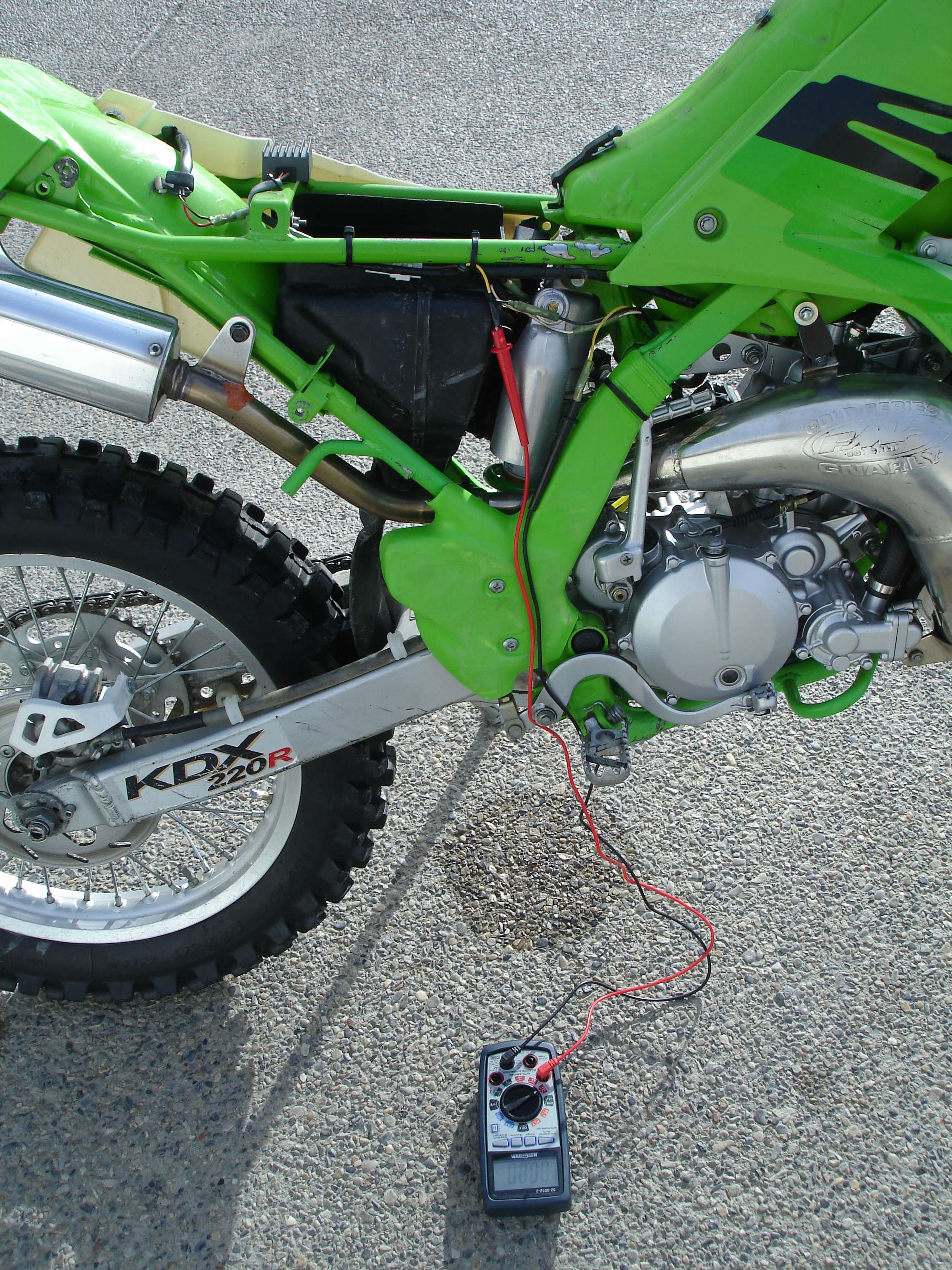
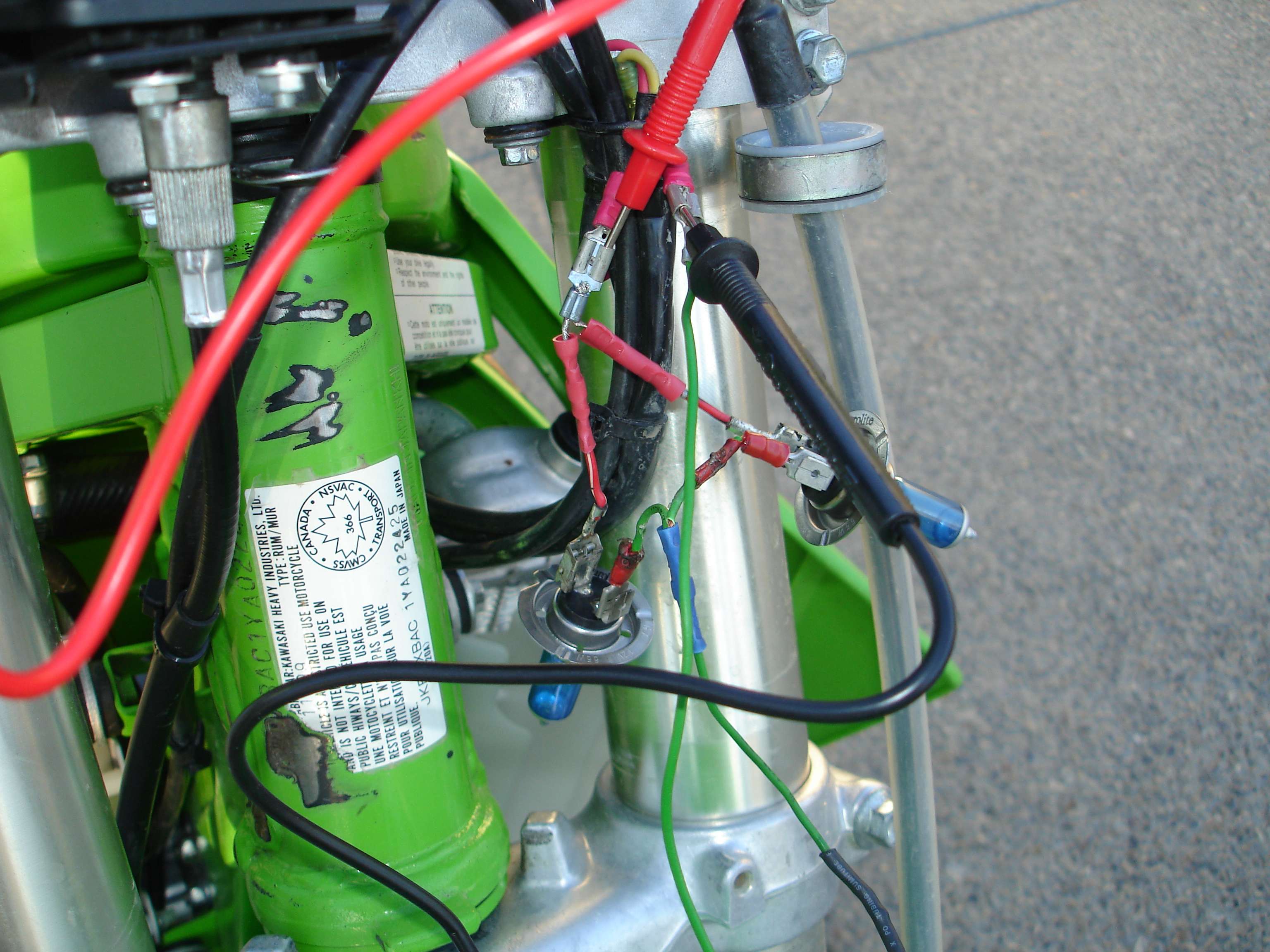
An AC voltmeter hooked into the headlight socket, in addition to the bulb(s) used for testing.
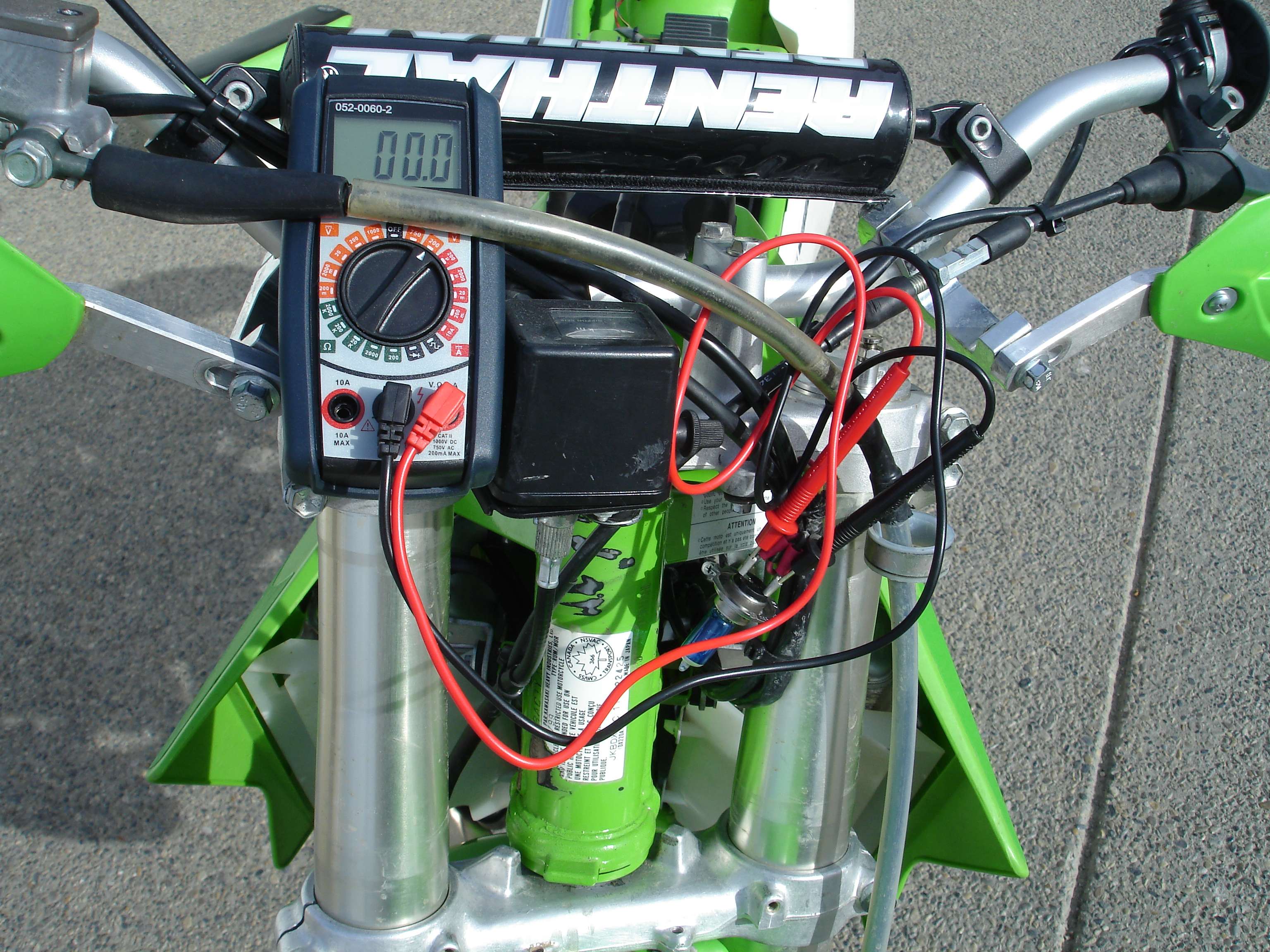
The bike easily put out 12.7vAC at a draw of only 4.17a.

Next, I decided to add a second H7 bulb in series with the first one, with the stock 10W tail light.
Here's where things get interesting. I don't think both bulbs were pulling a full 55W each, the math doesn't work out. More like 35W each. As I understand it, the bulbs will only take what's available, hence why they're not at full 55W brightness. There may have been 70W available to them, but it needs to be split now between the two bulbs.
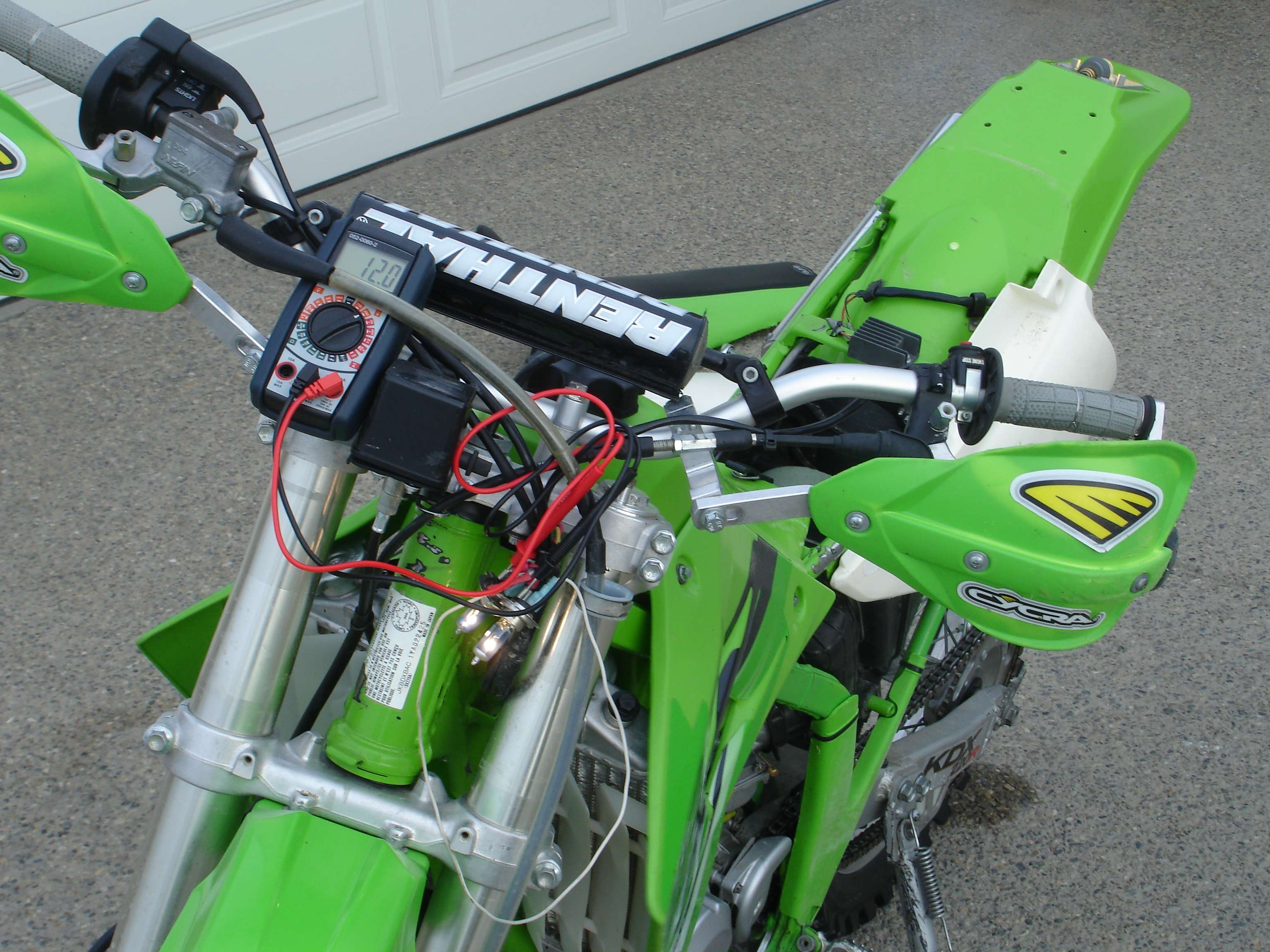
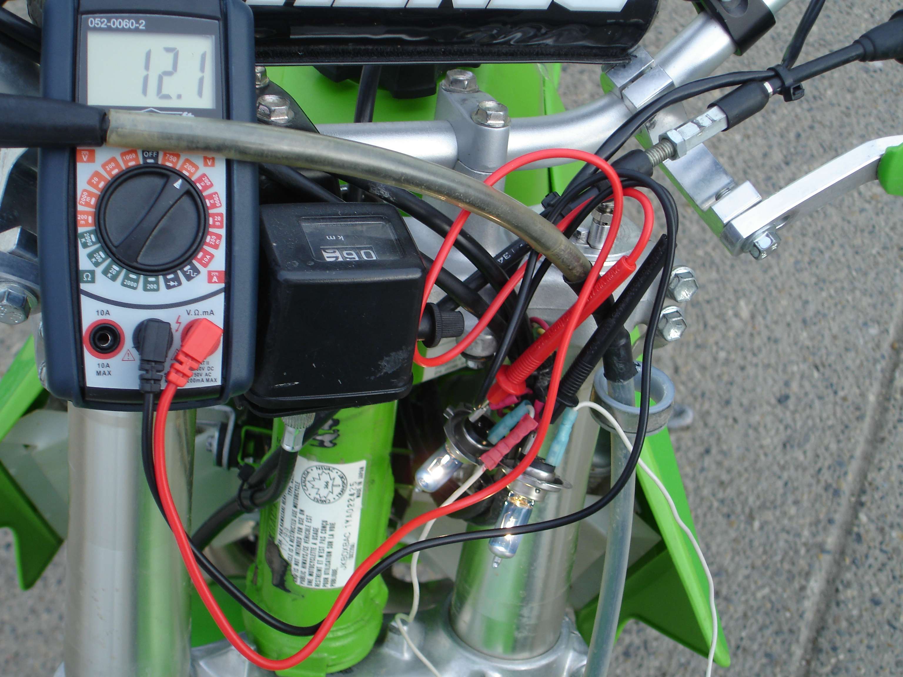
Anyway, with both H7's and the stock taillight, the stator put out an average of 12.3v, at 5.50a, at idle. (See youtube video, bottom of this post.)
Revved up very slightly, I got 12.4v and 6.60amps average. The stator is still able to maintain over 12V at idle, so I decided to add more draw.
I changed the tail light bulb to a 20W 1156, and found the breaking point. At idle, the bike could only maintain 11.8-12.0v with a current draw of 7.02a.
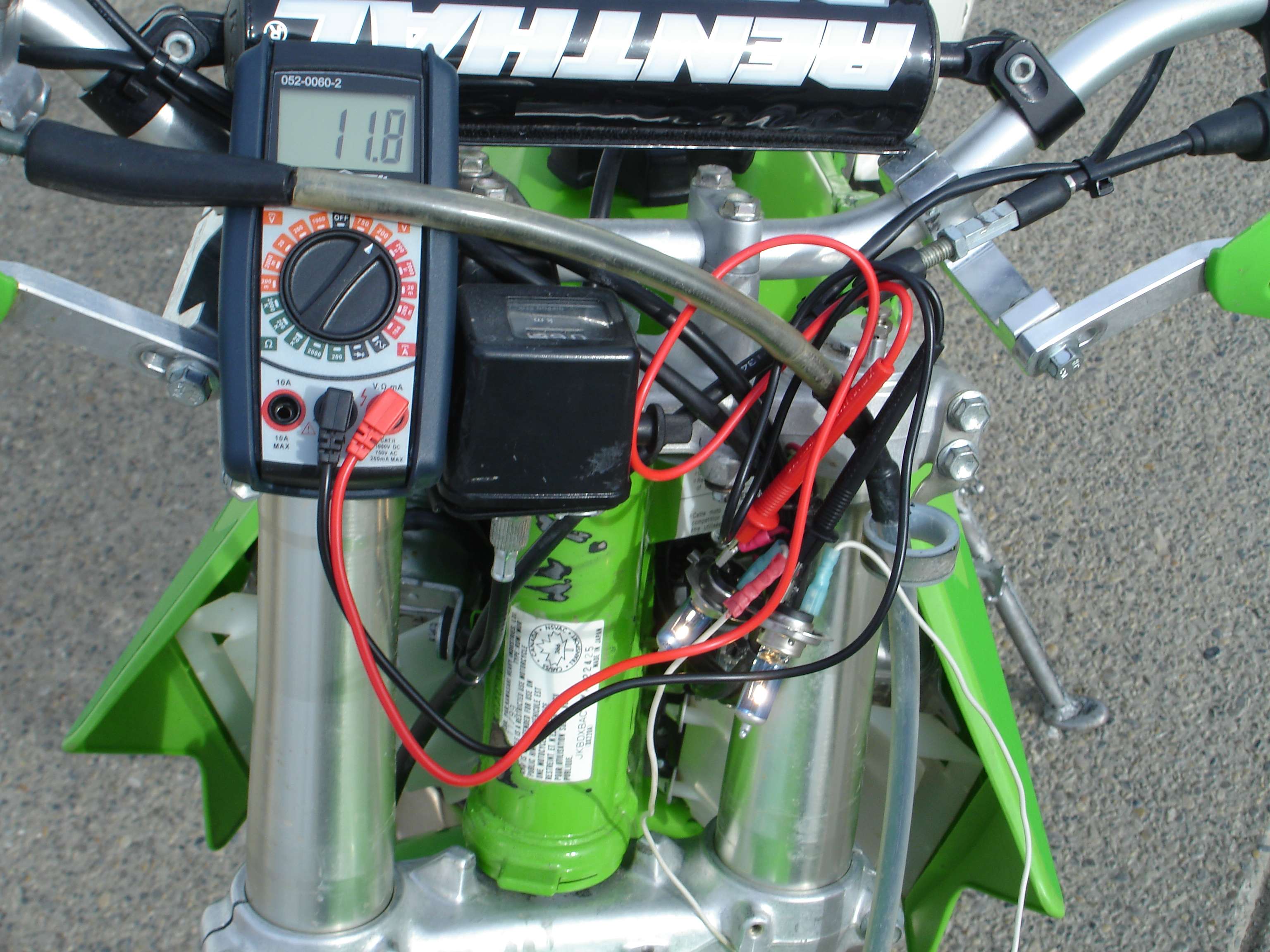
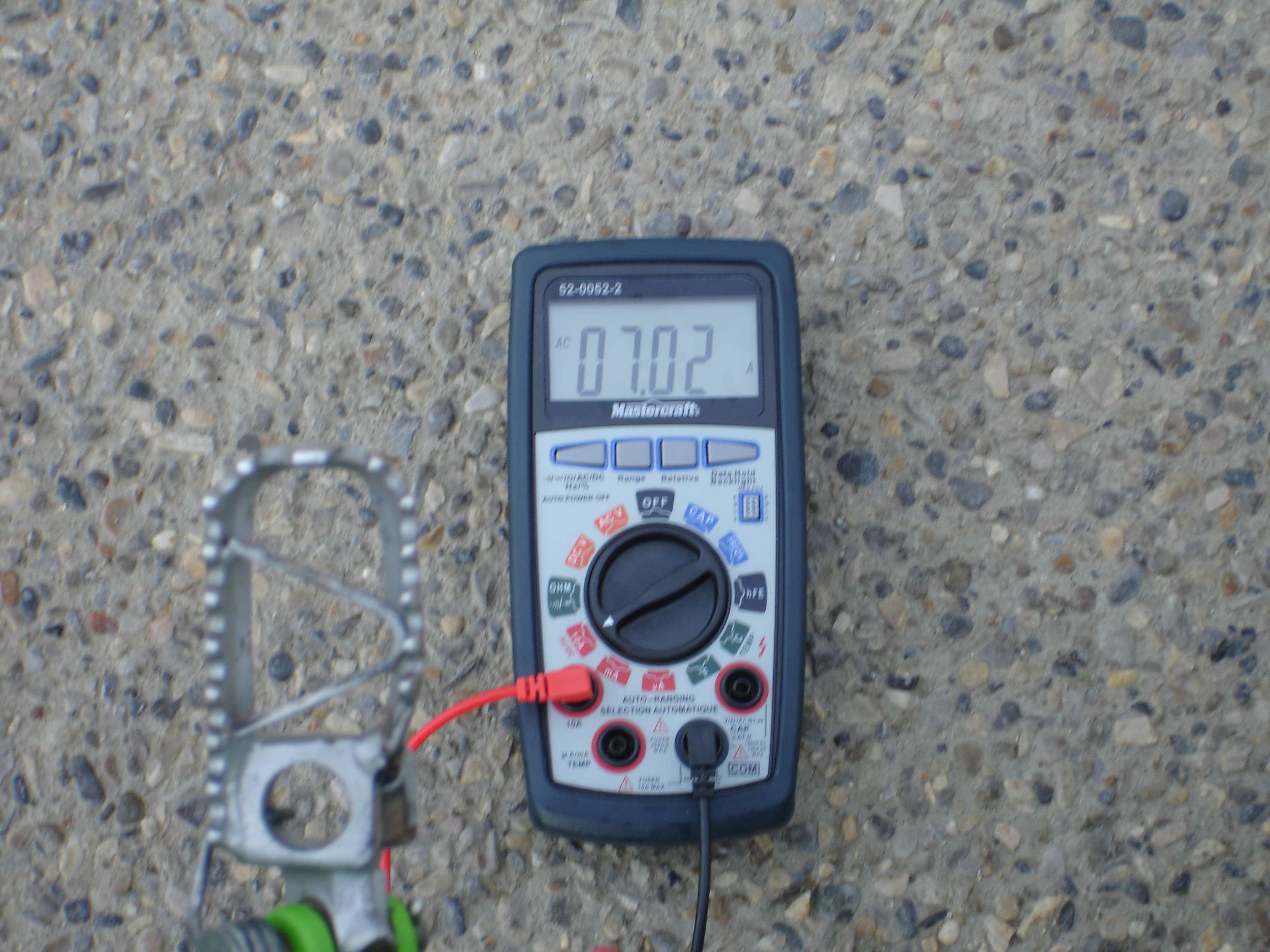
2 H7's and a 20W tail light bulb barely hits 12v:
Revved up slightly, the voltage was still struggling to get over 12v.
So, there it is. I had 2 55W H7 bulbs, in addition to the stock 10W tail light, and the stator "kept up." Figure each headlight bulb was getting about 35W apiece.
12.4v and 6.6a = 82W. That sounds right for two 35W headlights, and a 10W taillight to me.
12.3v and 5.5a = 68W at idle. I'm going to use these averages as just that, averages. In the middle. It's possible that the stator could put out a few more watts, or a few less.
Disclaimer:
Some may wonder why I took a reading with the bike slightly revved, and not solely at idle. The fact is, we ride, we don't idle. I don't care how bright my headlight is at a stop, I care about how bright it is while I rip down the trail. If I do care while I'm stopped, a quick flick of the wrist cures that. Capiche?
Conclusion:
MAX IDLE OUTPUT: 69W
MAX ACTUAL OUTPUT: 85W
Youtube video:
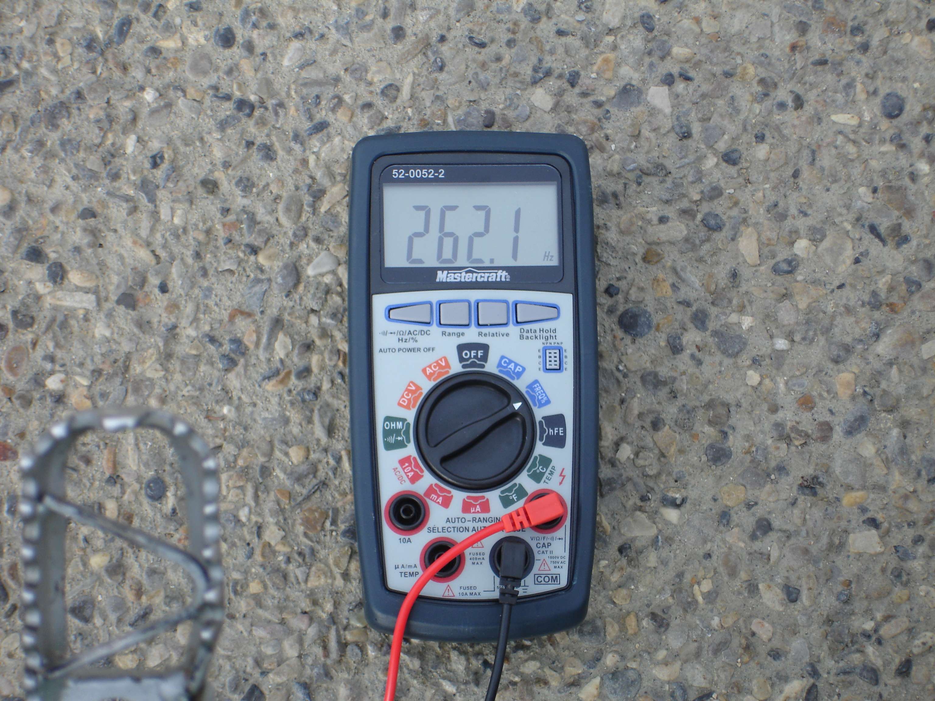
And for the electrical geeks, also took an electrical frequency reading at idle:
I went through a very systematic process today, and here are my findings:
First off, I started out by looking at my "stock" headlight, to see if there was any explanation for the extra current draw I was seeing before. Turns out, it was NOT a stock headlight, but a UFO unit. The way it was wired, was such that BOTH "high and low beam" fillaments were being used, at 35W each, for a total headlight draw of 70W. Note the lower fuse type bulb is not used, I'm talking about both fillaments in the main headlamp itself.
Onto the actual testing:
**All photos were taken at idle unless otherwise noted***
Knowing that my previous headlight was capable of pulling 70W, I knew 1 H7 bulb would be no problem @ 55W. I decided to try it anyway.
The test setup is as follows:
An AC multimeter setup to show AC current, wired in-line with the yellow wire coming off the lighting coil. This is the raw output right from the stator.
An AC voltmeter hooked into the headlight socket, in addition to the bulb(s) used for testing.
The bike easily put out 12.7vAC at a draw of only 4.17a.
Next, I decided to add a second H7 bulb in series with the first one, with the stock 10W tail light.
Here's where things get interesting. I don't think both bulbs were pulling a full 55W each, the math doesn't work out. More like 35W each. As I understand it, the bulbs will only take what's available, hence why they're not at full 55W brightness. There may have been 70W available to them, but it needs to be split now between the two bulbs.
Anyway, with both H7's and the stock taillight, the stator put out an average of 12.3v, at 5.50a, at idle. (See youtube video, bottom of this post.)
Revved up very slightly, I got 12.4v and 6.60amps average. The stator is still able to maintain over 12V at idle, so I decided to add more draw.
I changed the tail light bulb to a 20W 1156, and found the breaking point. At idle, the bike could only maintain 11.8-12.0v with a current draw of 7.02a.
2 H7's and a 20W tail light bulb barely hits 12v:
Revved up slightly, the voltage was still struggling to get over 12v.
So, there it is. I had 2 55W H7 bulbs, in addition to the stock 10W tail light, and the stator "kept up." Figure each headlight bulb was getting about 35W apiece.
12.4v and 6.6a = 82W. That sounds right for two 35W headlights, and a 10W taillight to me.
12.3v and 5.5a = 68W at idle. I'm going to use these averages as just that, averages. In the middle. It's possible that the stator could put out a few more watts, or a few less.
Disclaimer:
Some may wonder why I took a reading with the bike slightly revved, and not solely at idle. The fact is, we ride, we don't idle. I don't care how bright my headlight is at a stop, I care about how bright it is while I rip down the trail. If I do care while I'm stopped, a quick flick of the wrist cures that. Capiche?
Conclusion:
MAX IDLE OUTPUT: 69W
MAX ACTUAL OUTPUT: 85W
Youtube video:
And for the electrical geeks, also took an electrical frequency reading at idle:
'00 KDX 220R
-
TWMOODY
- Gold Member
- Posts: 752
- Joined: 08:10 pm Dec 01 2006
- Country:
- Location: Southeast , Michigan
Quote from Nick:
So, there it is. I had 2 55W H7 bulbs, in addition to the stock 10W tail light, and the stator "kept up." Figure each headlight bulb was getting about 35W apiece.
12.4v and 6.6a = 82W. That sounds right for two 35W headlights, and a 10W taillight to me.
12.3v and 5.5a = 68W at idle. I'm going to use these averages as just that, averages. In the middle. It's possible that the stator could put out a few more watts, or a few less.
Getting closer on the test but still not accurate and that's why you are "Figuring" each H7 was using "about" 35 watts of power.
The test with 1 H7 bulb was a good test !!
You did not say if the tail light bulb was in or not.
My guess is NO as you were only using 52.96 watts during this test.
The test with 2 H7 bulbs was no good thus your reasoning why the
" Math doesn't work out "
Those h7 bulbs needed to be placed in parallel to each other but series to the amp meter.
I just reread CHKDX post on the bulb set up and think he may have missed the point on that subject.
Anyhow
Nice testing again with just the 1 H7bulb and have to retest with 2
The reason the 2 h7's were as dim as they were is due to them sharing the available voltage, so each one was operating at just over 6 volts
Last edited by TWMOODY on 06:42 pm Feb 21 2011, edited 1 time in total.
-
Slick_Nick
- Supporting Member
- Posts: 1675
- Joined: 10:06 pm Oct 22 2009
- Country: Canada
- Location: Calgary, Alberta
- Contact:
-
rbates9

- Supporting Member II

- Posts: 3164
- Joined: 06:07 pm Apr 27 2010
- Country:
- Location: UPSTATE New York
I think that the point the OP was making was that you can make your own for cheap that puts out more power than stock. I think he did a great job showing everyone what to do and how to do it. Getting down to splitting watts don't really matter. If you want one that has a certified rating go buy one.
-
chkdx
- Supporting Member I
- Posts: 132
- Joined: 09:31 pm Oct 02 2009
- Country:
- Location: Carson City, NV
Yep, to increase current draw you add bulbs in parallel with each other while keeping them in series with the ammeter. No matter though, by trying different bulb combinations you ended up with very accurate tests. The stator doesn't know or care HOW a given resistance is established, it simply reacts to the resistance it sees.
Good job, and it's great info to have, thanks!
Good job, and it's great info to have, thanks!
-
TWMOODY
- Gold Member
- Posts: 752
- Joined: 08:10 pm Dec 01 2006
- Country:
- Location: Southeast , Michigan
Slick_Nick wrote:In series to the amp meter? They are in series with the amp meter. Why do the bulbs need to be wired in paralell?
Because the bulbs are designed to operate at around 12 volts.
Setting them up in series each one only gets that 12 volts divided by the number of bulbs in the system IE:
At 12 volts
2 bulbs in series - each one only gets 6 volts
3 bulbs in series - each one only gets 4 volts
That's why the bulbs got so dim when you put the second on in line.
-
TWMOODY
- Gold Member
- Posts: 752
- Joined: 08:10 pm Dec 01 2006
- Country:
- Location: Southeast , Michigan
rbates9 wrote:I think that the point the OP was making was that you can make your own for cheap that puts out more power than stock. I think he did a great job showing everyone what to do and how to do it. Getting down to splitting watts don't really matter. If you want one that has a certified rating go buy one.
I think the idea here is to establish what the actual gains Nick has
accomplished with his rewind as it seems to have a pretty wide
range of interest on the site.
Getting down to splitting watts really DOES really matter and that's why
there are the specific questions and Nick is doing a pretty good job
of testing his work and providing documented evidence to support his
claims.
Kudo's to Nick going through and answering all the questions and
if it really don't matter to you Bates why you wasting your time reading this thread ?
-
SS109
- KDXRider.net
- Posts: 5796
- Joined: 05:11 am Aug 23 2009
- Country: USA
- Location: Tucson, AZ, USA
- Contact:
Great stuff, Nick! 


For me the important thing is that we know it will pull at least 55 watts and that is a helluva lot more than the stock stator can do! That is a serious improvement for very little cash investment. I'm willing to bet it will spec out at least as good as the aftermarket stators (60-65 watts) we see for sale. Of course, I would love to see it put out 70-80+ watts so I hope the testing continues!
For me the important thing is that we know it will pull at least 55 watts and that is a helluva lot more than the stock stator can do! That is a serious improvement for very little cash investment. I'm willing to bet it will spec out at least as good as the aftermarket stators (60-65 watts) we see for sale. Of course, I would love to see it put out 70-80+ watts so I hope the testing continues!
Youtube Channel: WildAzzRacing
AZ State Parks & Trails OHV Ambassador - Trail Riders of Southern AZ
Current KDX: '98 KDX220
Old KDX: '90 KDX200 -White/Blue
'11 GasGas EC250R
AZ State Parks & Trails OHV Ambassador - Trail Riders of Southern AZ
Current KDX: '98 KDX220
Old KDX: '90 KDX200 -White/Blue
'11 GasGas EC250R
-
Slick_Nick
- Supporting Member
- Posts: 1675
- Joined: 10:06 pm Oct 22 2009
- Country: Canada
- Location: Calgary, Alberta
- Contact:
Well, I'm back with what are hopefully the final results!
I wired both headlights up in paralell this time. Please excuse the jimmy-rigged wiring harness, I put it together with a bunch of pieces I had lying around in about 90 seconds. It worked!
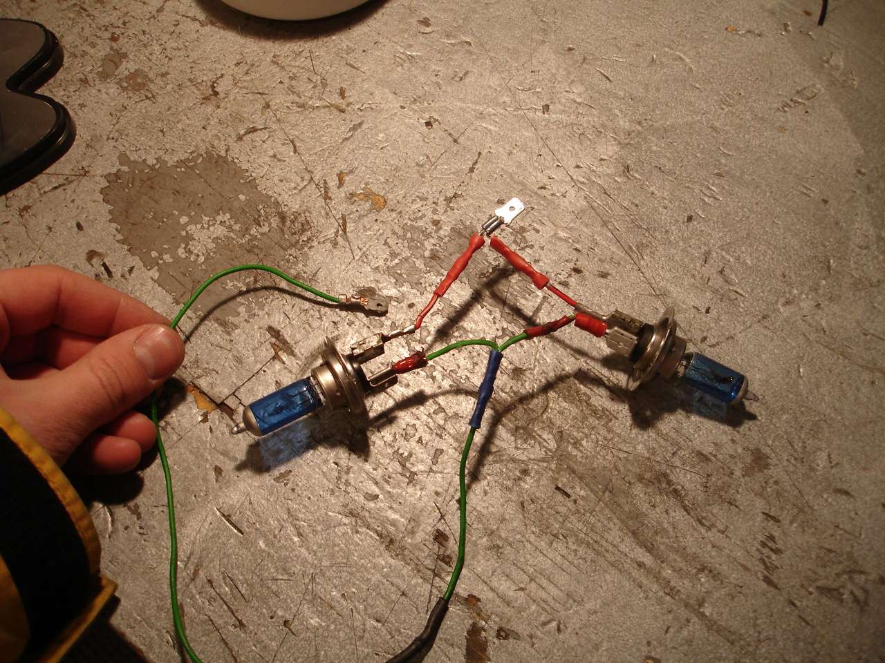
Ok, so I have the multimeters set up just like before, the current reading taken tirectly from the yellow wire, and the voltage reading taken directly from the main headlight harness, before it splits to each bulb. My results may surprise you, I know they surprised me!
It's important to note that this time a taillight bulb was NOT installed!
Onto the test!
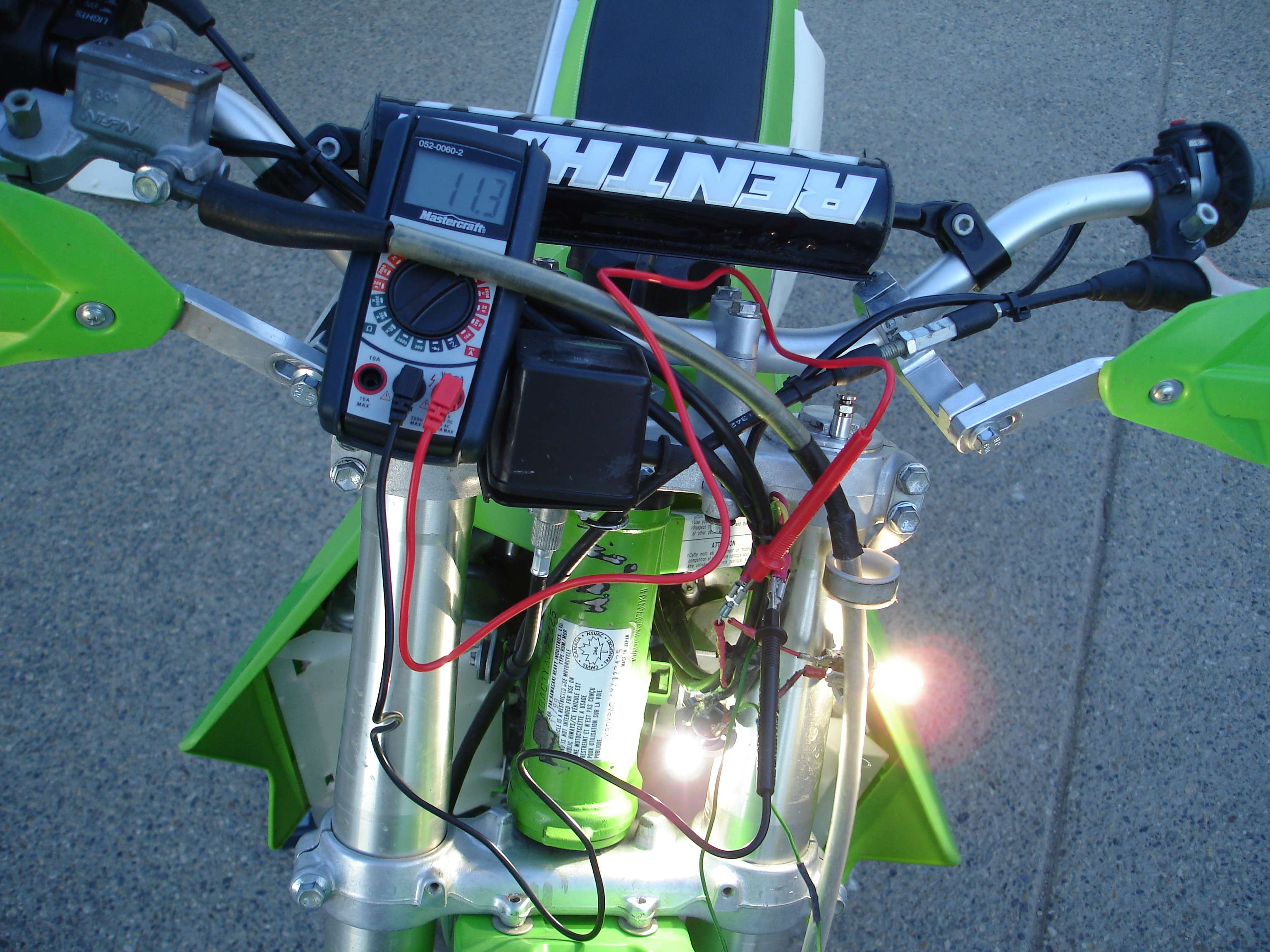
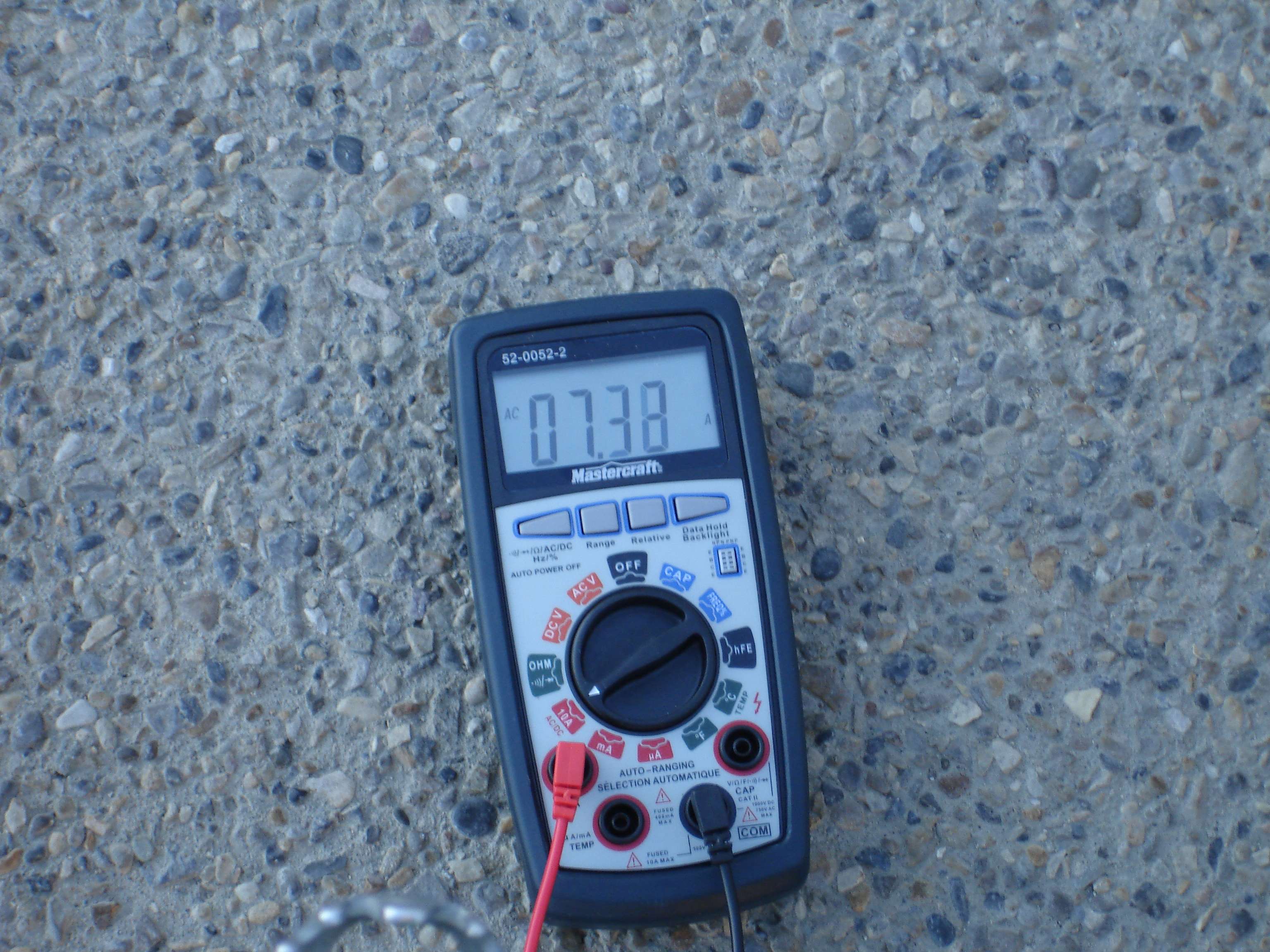
I started the bike, let it warm up (it's a chilly -10 here right now!) and then took my readings, so everything was as it would be if you were going riding. This time, the bulbs were in fact much brighter. At idle, the stator can not sustain 12V with both bulbs hooked up. I saw 11.3v at 7.33a.
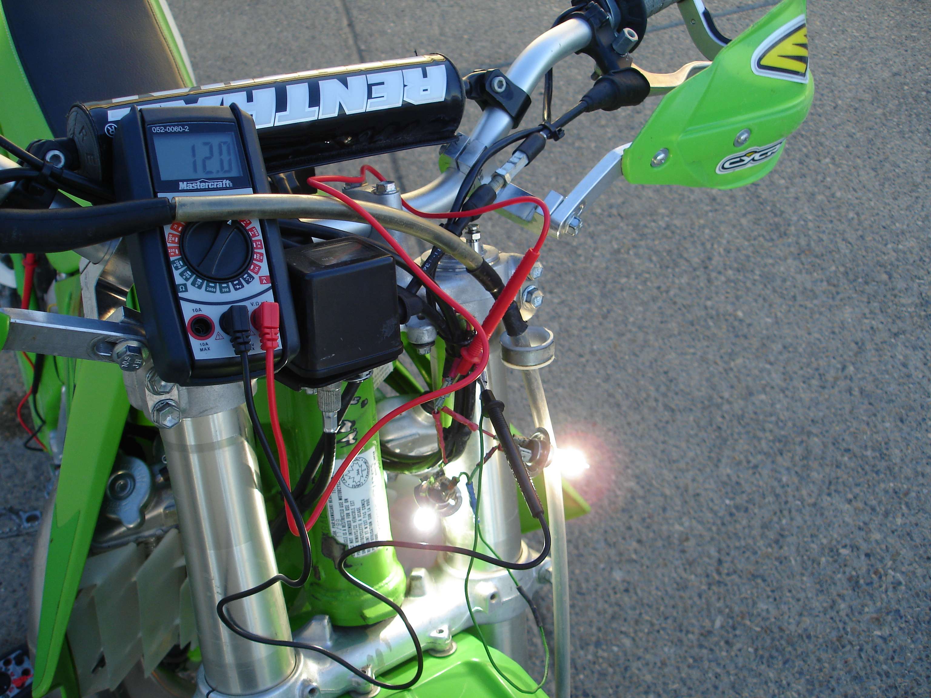
Well below the minimum 12v, but we want to see how many watts we can support at 12v. I revved the engine ever so slightly and voila! 12.0v appeared, a few hundred RPM above idle. A quick check of the amperage being drawn showed 7.69a. Both bulbs were burning bright as hell too!

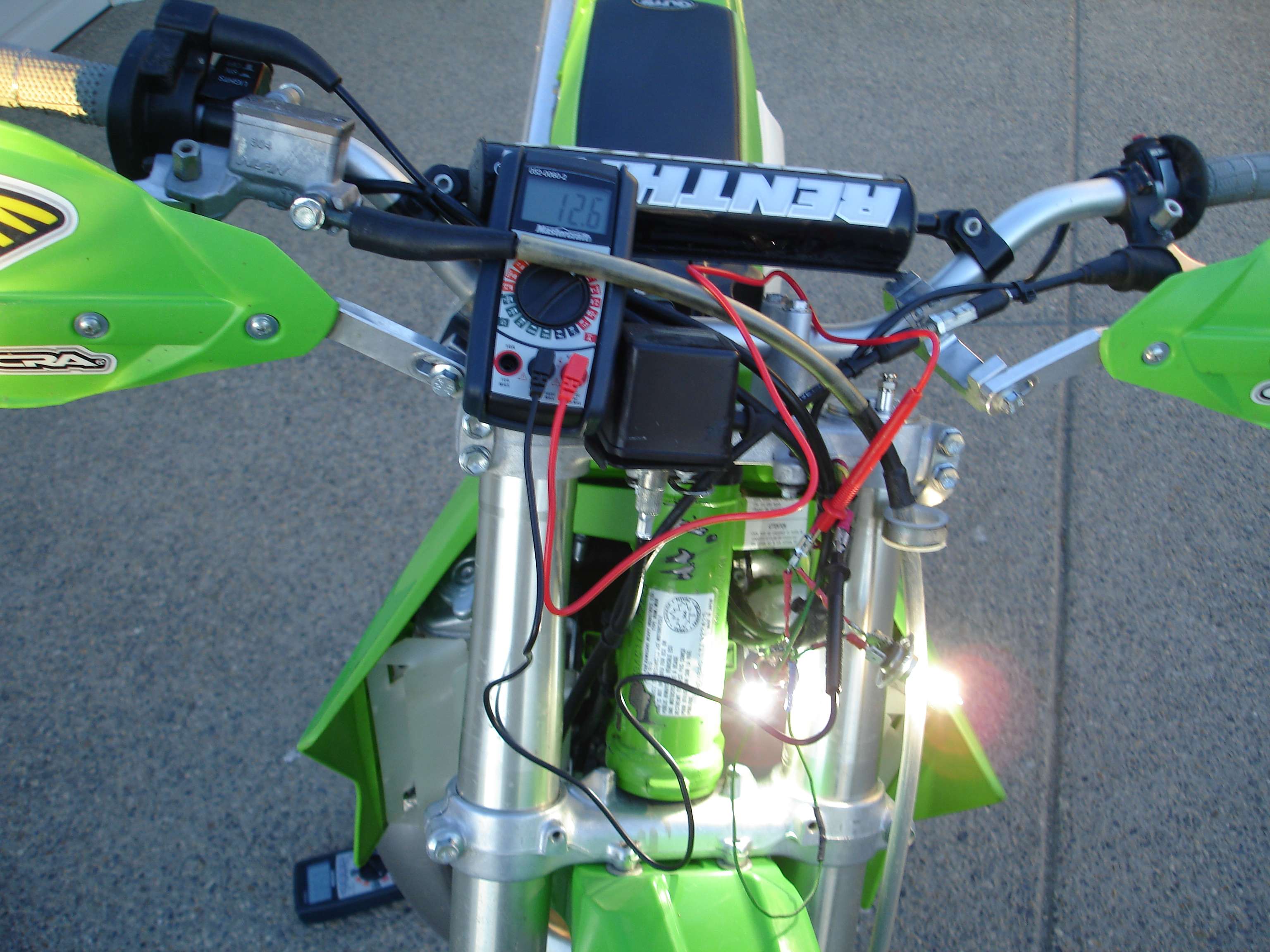
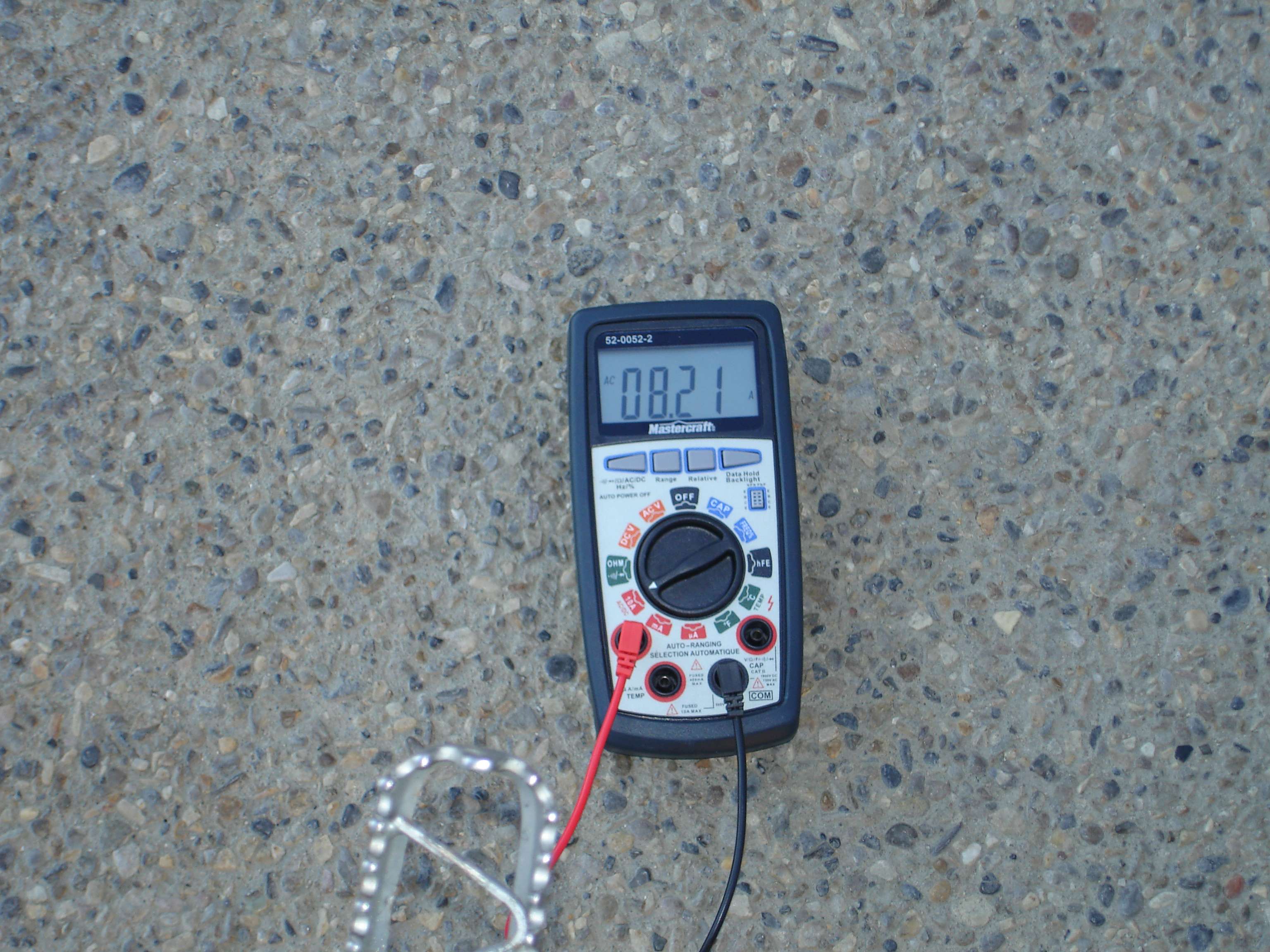
Then I got greedy, I wanted to see what the stator could really do. I revved it even higher, and (you're not gonna believe this!) I was shown 12.6v at 8.21a! That's 103W!
Now, I'll reiterate that the only electrical equipment installed were the two headlights, the tail light was removed. The final reading was taken at an RPM that you probably wouldn't cruise at, but it's nice to see that the stator is at least capable of that much!
So, what does this all mean...
Well, when we look at our three test samples:
Idle - 11.3v at 7.33a = 83W
Just above idle - 12.0v at 7.69a = 92W
Riding RPM - 12.6v at 8.21a = 103W
Obviously, it's a generator, and like any generator, output varies with RPM. So, lets compare these results with my previous tests, and see what we come up with. While the voltage did drop at idle compared to my previous tests, the current also increased, and we all know that voltage x current = watts, so I ended up with wattage outputs that weren't too far off from each other, which makes sense. A coil is a coil, and at a given RPM will only put out a certain number of watts. How those watts are distributed between voltage and current doesn't seem to matter as much, it can only put out X watts at Y RPM. CHkdx was correct in the sense that it doesn't care how the power is distributed after that.
Now, I had this curcuit loaded up with a potential 110W draw. That's huge. Think about that. That's a set of car headlights! I wanted to see at what point the upgraded stator would fail, and I believe in this sense, I exceeded it. I wasn't able to fully pull 110W out of the coil, and even the 103W I did get were at riding RPM, and really, to me, having the brightness just above idle is where it counts. Like the stock stator, there was a noticeable change in brightness as RPM's got higher. Come to think of it, There really would be no way to measure it, but with this coil having to supply over 100W of power, it's going to get HOT! I don't know that you'd want a coil that is going to make much more heat than that, in an enclosed case with no airflow.
So what is it? A 100W stator? An 80W stator? That's up to you. What I can tell through my experimentation, is that the coil is physically capable of putting out over 100W of power. Would I run two 50W bulbs on it everyday? Probably not, but the power is there. I run a 70W headlight, and a 10W tail light. That's good enough for me. It doesn't dim too bad, or flicker at idle, and 70W of headlight is plenty for the amount of time I'm stuck in the bush after dark.
I learned a LOT in doing these tests, I was pleasently surprised at some results. While there has been a lot of trial and error, checking and re-checking, picture taking and note taking, in the end I find it very rewarding. For a minimal investment, I've created a lighting coil for the KDX that's almost twice as powerful as the stock one, and learned a ton about how the bike works. That's good enough for me!
I wired both headlights up in paralell this time. Please excuse the jimmy-rigged wiring harness, I put it together with a bunch of pieces I had lying around in about 90 seconds. It worked!
Ok, so I have the multimeters set up just like before, the current reading taken tirectly from the yellow wire, and the voltage reading taken directly from the main headlight harness, before it splits to each bulb. My results may surprise you, I know they surprised me!
It's important to note that this time a taillight bulb was NOT installed!
Onto the test!
I started the bike, let it warm up (it's a chilly -10 here right now!) and then took my readings, so everything was as it would be if you were going riding. This time, the bulbs were in fact much brighter. At idle, the stator can not sustain 12V with both bulbs hooked up. I saw 11.3v at 7.33a.
Well below the minimum 12v, but we want to see how many watts we can support at 12v. I revved the engine ever so slightly and voila! 12.0v appeared, a few hundred RPM above idle. A quick check of the amperage being drawn showed 7.69a. Both bulbs were burning bright as hell too!
Then I got greedy, I wanted to see what the stator could really do. I revved it even higher, and (you're not gonna believe this!) I was shown 12.6v at 8.21a! That's 103W!
Now, I'll reiterate that the only electrical equipment installed were the two headlights, the tail light was removed. The final reading was taken at an RPM that you probably wouldn't cruise at, but it's nice to see that the stator is at least capable of that much!
So, what does this all mean...
Well, when we look at our three test samples:
Idle - 11.3v at 7.33a = 83W
Just above idle - 12.0v at 7.69a = 92W
Riding RPM - 12.6v at 8.21a = 103W
Obviously, it's a generator, and like any generator, output varies with RPM. So, lets compare these results with my previous tests, and see what we come up with. While the voltage did drop at idle compared to my previous tests, the current also increased, and we all know that voltage x current = watts, so I ended up with wattage outputs that weren't too far off from each other, which makes sense. A coil is a coil, and at a given RPM will only put out a certain number of watts. How those watts are distributed between voltage and current doesn't seem to matter as much, it can only put out X watts at Y RPM. CHkdx was correct in the sense that it doesn't care how the power is distributed after that.
Now, I had this curcuit loaded up with a potential 110W draw. That's huge. Think about that. That's a set of car headlights! I wanted to see at what point the upgraded stator would fail, and I believe in this sense, I exceeded it. I wasn't able to fully pull 110W out of the coil, and even the 103W I did get were at riding RPM, and really, to me, having the brightness just above idle is where it counts. Like the stock stator, there was a noticeable change in brightness as RPM's got higher. Come to think of it, There really would be no way to measure it, but with this coil having to supply over 100W of power, it's going to get HOT! I don't know that you'd want a coil that is going to make much more heat than that, in an enclosed case with no airflow.
So what is it? A 100W stator? An 80W stator? That's up to you. What I can tell through my experimentation, is that the coil is physically capable of putting out over 100W of power. Would I run two 50W bulbs on it everyday? Probably not, but the power is there. I run a 70W headlight, and a 10W tail light. That's good enough for me. It doesn't dim too bad, or flicker at idle, and 70W of headlight is plenty for the amount of time I'm stuck in the bush after dark.
I learned a LOT in doing these tests, I was pleasently surprised at some results. While there has been a lot of trial and error, checking and re-checking, picture taking and note taking, in the end I find it very rewarding. For a minimal investment, I've created a lighting coil for the KDX that's almost twice as powerful as the stock one, and learned a ton about how the bike works. That's good enough for me!
'00 KDX 220R
-
Slick_Nick
- Supporting Member
- Posts: 1675
- Joined: 10:06 pm Oct 22 2009
- Country: Canada
- Location: Calgary, Alberta
- Contact:
-
chkdx
- Supporting Member I
- Posts: 132
- Joined: 09:31 pm Oct 02 2009
- Country:
- Location: Carson City, NV
VERY impressive Nick!
Your test was very accurate, and truly shows what your rewound stator can do. Great job!
My one small concern (don't you HATE it when someone says that?!) is that just possibly if the headlight and tail light bulbs burn out, and the shunt regulator starts dumping a bunch of current to ground to maintain 12.5 volts, the regulator itself may fail. There's really no way to test this theory, short of stressing a regulator with ever higher amps until failure, then saying "Ok, this regulator can handle X amount of amps.", then buying another, but I just want you to be aware of the possibility.
Personally, I'd just run the sucker as is and see how it works on the trail for ya.
-
SS109
- KDXRider.net
- Posts: 5796
- Joined: 05:11 am Aug 23 2009
- Country: USA
- Location: Tucson, AZ, USA
- Contact:
Freakin' awesome results Nick! You da' man for going through all the trouble to get accurate readings. This makes me feel very good about running my new Polisport headlight (which I can get up to a 60 watt bulb for) and my LED tail/brake light! Hell yeah!
Youtube Channel: WildAzzRacing
AZ State Parks & Trails OHV Ambassador - Trail Riders of Southern AZ
Current KDX: '98 KDX220
Old KDX: '90 KDX200 -White/Blue
'11 GasGas EC250R
AZ State Parks & Trails OHV Ambassador - Trail Riders of Southern AZ
Current KDX: '98 KDX220
Old KDX: '90 KDX200 -White/Blue
'11 GasGas EC250R
-
Slick_Nick
- Supporting Member
- Posts: 1675
- Joined: 10:06 pm Oct 22 2009
- Country: Canada
- Location: Calgary, Alberta
- Contact:
The stator itself is not generating any power unless the headlight switch is actually on, which for me is only about 20% of the time. I'm not too worried about the VR, if it pops, new ones are cheap on ebay!
It's worthwhile to note that I also noticed a marked improvement in lower end "pep" and I've been able to run a spark plug gap that's much wider, which may contribute to this. I've read that a bigger lighting coil can help excite the ignition coil as well, leading to what I've experienced. As an electrical engineer, what are your thoughts on that?
It's worthwhile to note that I also noticed a marked improvement in lower end "pep" and I've been able to run a spark plug gap that's much wider, which may contribute to this. I've read that a bigger lighting coil can help excite the ignition coil as well, leading to what I've experienced. As an electrical engineer, what are your thoughts on that?
'00 KDX 220R